Underwater motive device

a motive device and underwater technology, applied in underwater equipment, marine propulsion, vessel construction, etc., can solve the problems of large underwater motive devices, large size, bulky, etc., and achieve the effect of easy removal and replacement and long battery li

Inactive Publication Date: 2005-02-01
HYDRODYNAMIC INDAL
View PDF2 Cites 10 Cited by
  • Summary
  • Abstract
  • Description
  • Claims
  • Application Information

AI Technical Summary

Benefits of technology

An underwater motive device utilizes a plastic rear housing which includes a battery storage space which is “o” ring sealable with a front wall. Because the “o” ring seal is multiple and of tight fit to provide sealing, a pressured removal system is provided to pressurize the sealed battery chamber to enable the front wall to be removed. The battery is not only readily accessible for charging or replacement, but the front wall is easily removed and replaced. The motor is microprocessor controlled for safety by providing a slight delay before energizing the motor, and by providing some time in residence at a slow speed before switching to a higher speed. The result is a safe underwater motive device which will not accidentally become power actuated before the user is able to securely grasp and direct it, and which will not go to full speed except from a low speed to give the user a chance to stabilize himself in the water. Further, the control circuitry includes other features to provide both long battery life, good serviceable usage and battery preservation and motor preservation. The control circuit preferably constantly monitors the current through the motor and shuts down the motor if the current rises above a predetermined level. The circuit preferably constantly monitors the battery voltage and shuts down if the voltage is less than a predetermined level. The circuit preferably constantly measures the temperature of the motor and shuts down if the temperature is above a certain predetermined level. Further, the circuit will preferably constantly measure the rate of change of the current and shut down of the rate of change of current is above a predetermined level, the rate change being either positive (increasing current) or negative (decreasing current). Further, the circuit uses two reed switches that can be independently switched to their conducting state and it is preferred that both must be conducting for the motor to be switched on.

Problems solved by technology

As a result, the underwater motive devices were large, bulky and designed with a mind to limit outside access to limit the sealing areas provided for service access.
The early underwater motive devices were also expensive, and heavy such that the only effective market was professional divers because of both the cost and strength required to handle the unit under water.
Because of the sealed nature of the units, rechargeablility caused considerable time in opening, inspecting and re-sealing the units.
Instant-on full power was another reason that the early underwater motive devices were dangerous due to increased lack of controllability.
The user had to be skillful to avoid being raked by nearby objects in addition to other user problems.
Another early problem was ballast.
Adjusting the ballast was a problem because each time an adjustment was desired to be made, it involved a complicated breaching of the sealed outer housing.

Method used


Image

  • Underwater motive device
  • Underwater motive device
  • Underwater motive device

Examples


Embodiment Construction

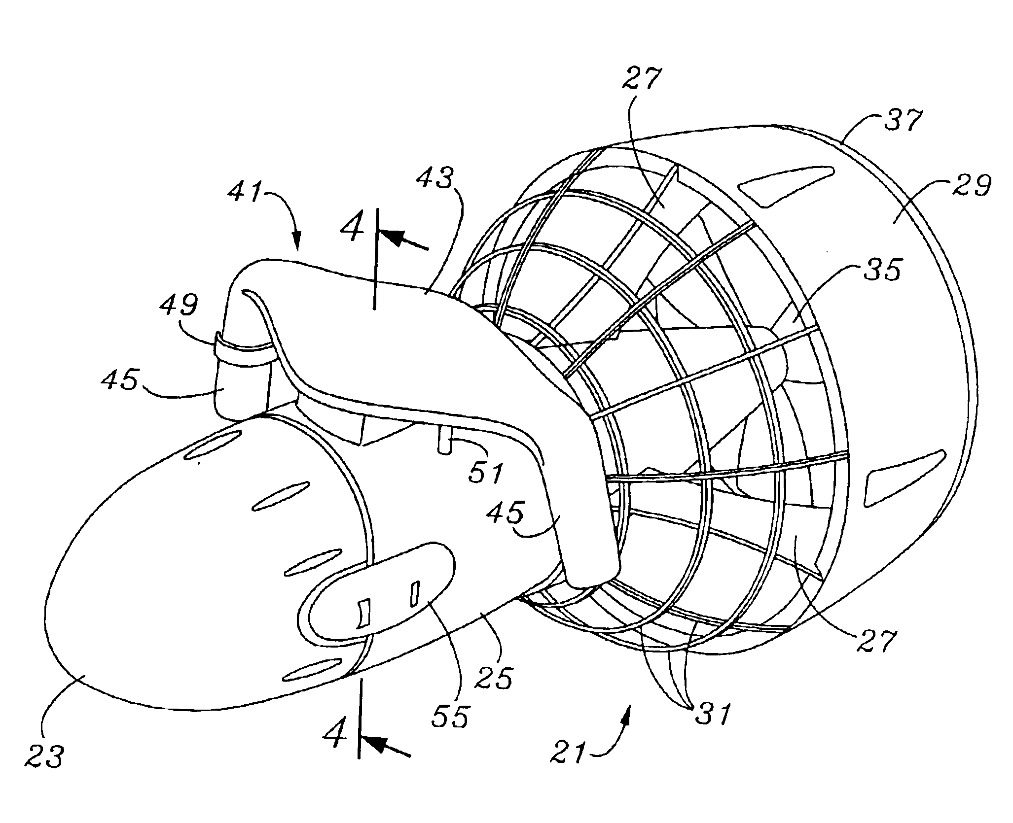
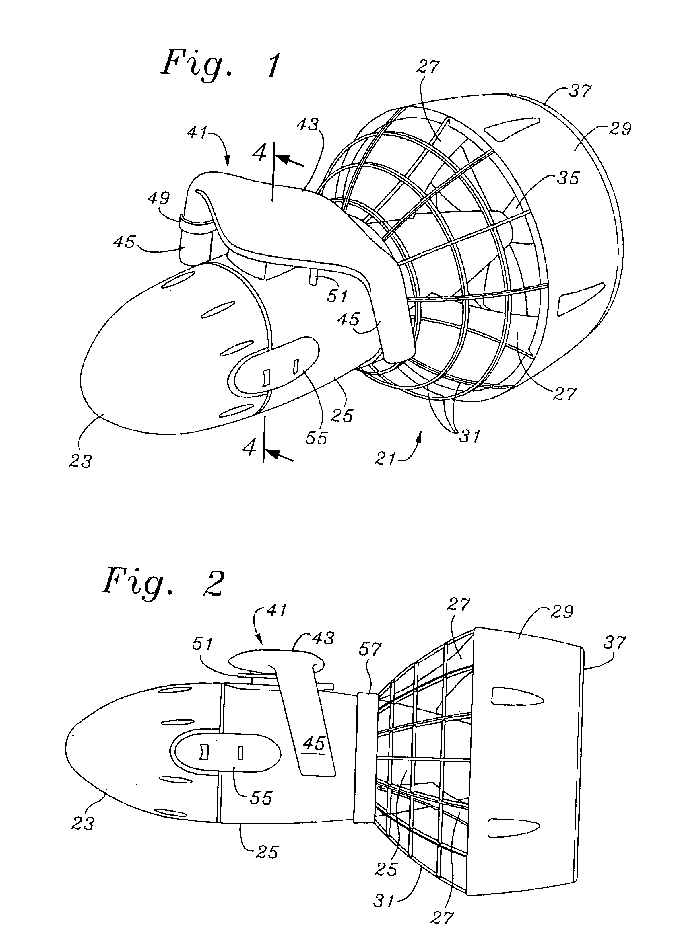
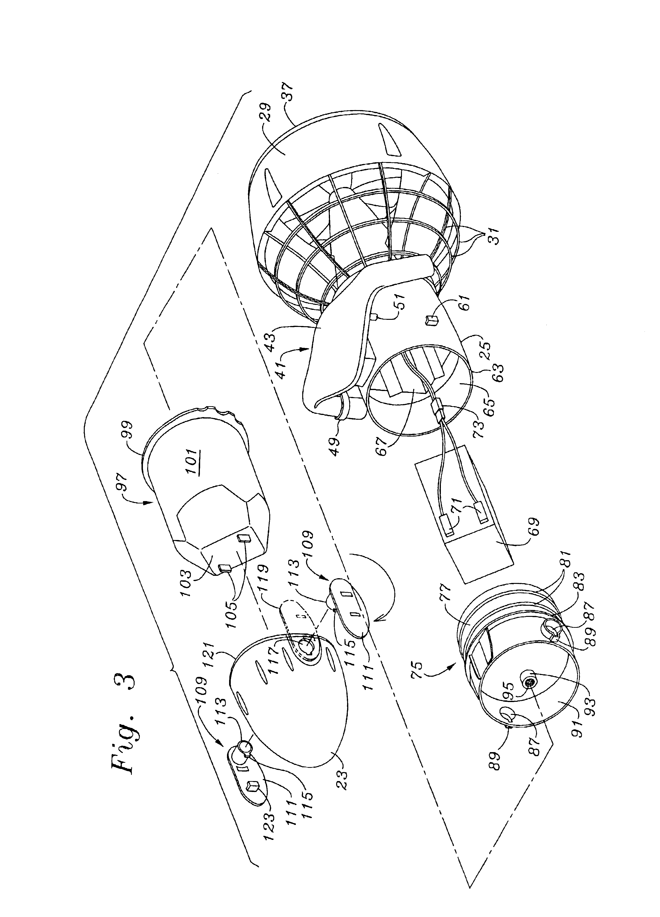
The description and operation of the invention will be best initiated with reference to FIG. 1. An underwater motive device 21 has housing members including a front cone 23 and rear main housing 25. From the rear main housing 25 a number of fan housing supports 27 support a fan housing 29. In addition to the fan housing supports 27, a cage 31 provides stability to the fan housing 29, and is supported by it.

The rear main housing 25 extends somewhat rearwardly of the cage 31 and rotatably supports a propeller 35. A rearmost screen guard 37 is only partially see at the rearward rim of the fan housing 29 and is excluded from being shown adjacent the propeller 35 for clarity.

At the top of the rear main housing 25 is a handle bar support 41 which includes a top generally hydrodynamic area 43 leading to a pair of oppositely disposed handle bars 45 which are angled slightly rearwardly along their downward path extent. The handle bars 45 are intended to be grasped with the underwater motive ...


PUM


Abstract

An underwater motive device utilizes a plastic rear housing which includes a battery storage space sealed with a tight fit to provide sealing, a pressured removal system is provided to pressurize the sealed battery chamber to enable the front wall to be removed. The motor is microprocessor controlled for safety by providing a slight delay before energizing the motor, and by providing some time in residence at a slow speed before switching to a higher speed. The result is a safe underwater motive device which will not accidentally become power actuated before the user is able to securely grasp and direct it, and which will not go to full speed except from a low speed to give the user a chance to stabilize himself in the water. Further, the control circuitry includes other features to provide both long battery life, good serviceable usage and battery preservation and motor preservation.

Description

FIELD OF THE INVENTIONThe present invention relates to improvements in the technology relating to in water and underwater mechanical motive structures and particularly to improvements relating to a battery powered device for propelling swimmers and divers forward.BACKGROUND OF THE INVENTIONUnderwater motive devices have been known since the 1950's. Most of those earlier devices were metal and were built like small submarines. Access was had through hatches which had to be securely bolted or clamped in order to resist taking on water at depth. As a result, the underwater motive devices were large, bulky and designed with a mind to limit outside access to limit the sealing areas provided for service access.The early underwater motive devices were also expensive, and heavy such that the only effective market was professional divers because of both the cost and strength required to handle the unit under water. Because of the sealed nature of the units, rechargeablility caused considerab...

Claims


Application Information

Patent Timeline
Patent Type & Authority Patents(United States)
IPC IPC(8): A63B35/12A63B35/00B63C11/46
CPCB63C11/46A63B35/12B63C2011/028
Inventor MAH, PAT Y.
Owner HYDRODYNAMIC INDAL
Why Eureka
Try Eureka