Electronic controlled coupling

Inactive Publication Date: 2005-02-01
KOYO SEIKO CO LTD +1
View PDF10 Cites 45 Cited by
  • Summary
  • Abstract
  • Description
  • Claims
  • Application Information

AI Technical Summary

Benefits of technology

Accordingly, it is an object of the present invention to increase the durability of an electronic controlled coupling that includes a hydraulic wet-

Problems solved by technology

Thus, the discharge pressure of the oil pump directly affect

Method used


Image

  • Electronic controlled coupling
  • Electronic controlled coupling
  • Electronic controlled coupling

Examples


first embodiment

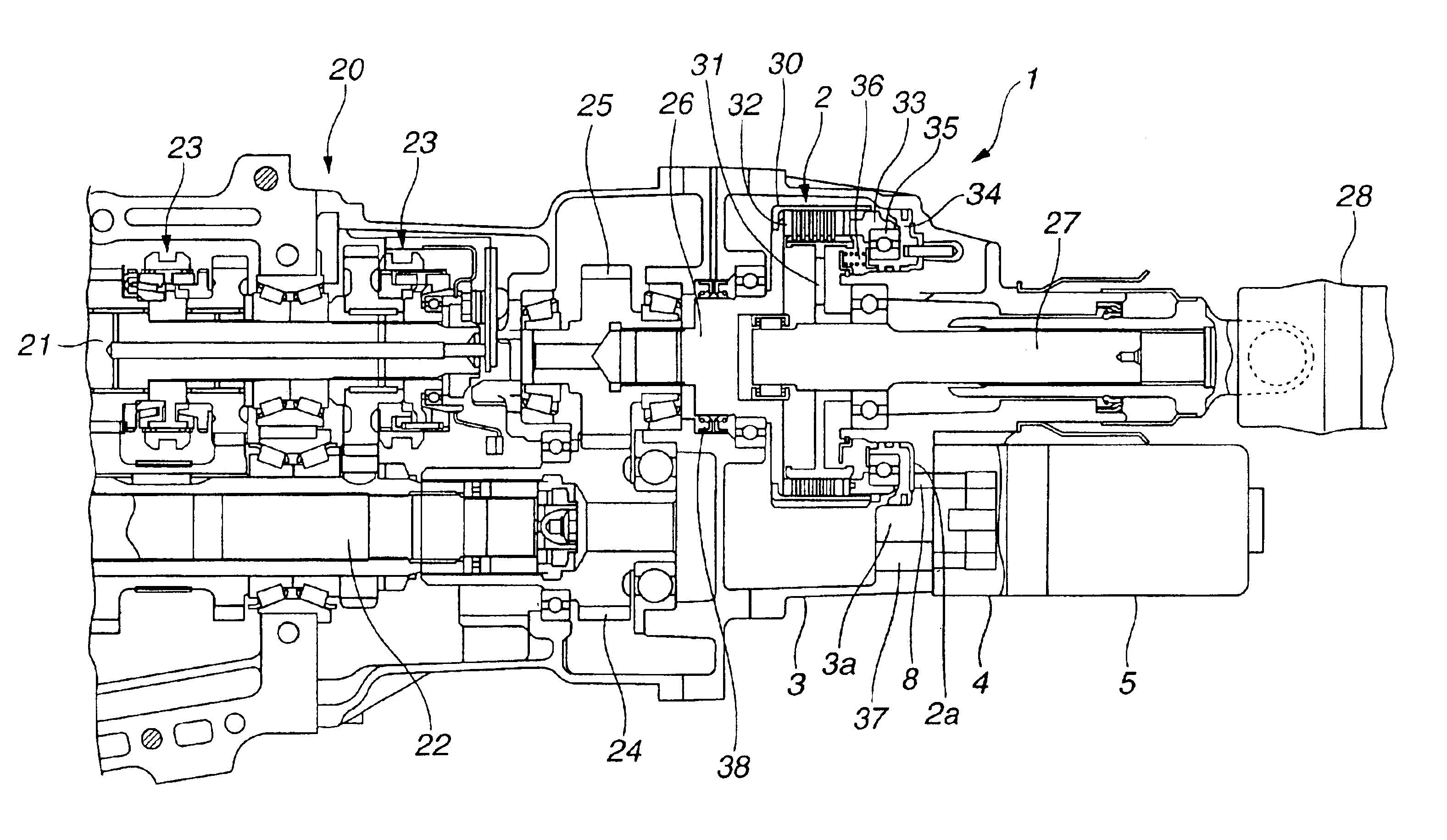
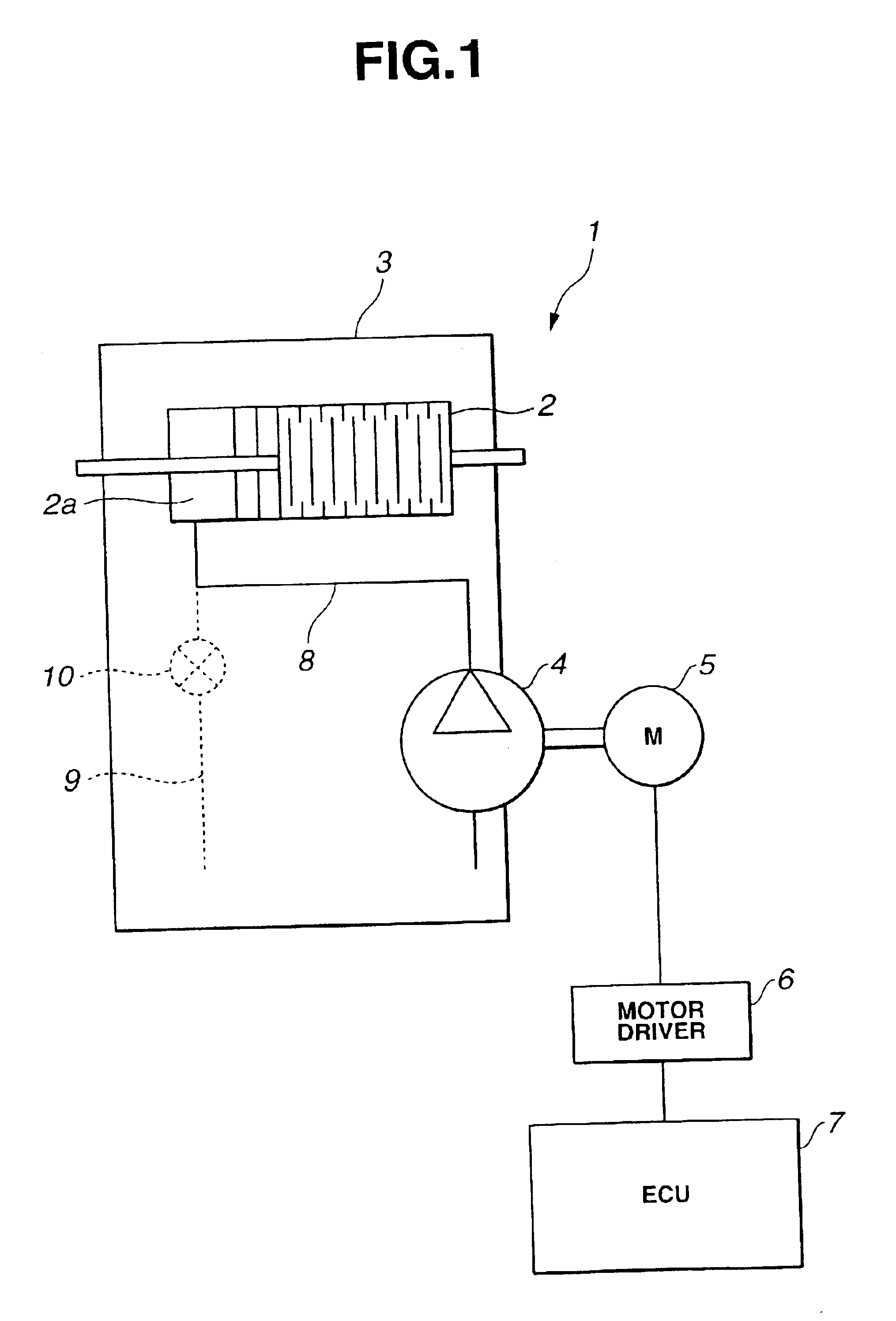
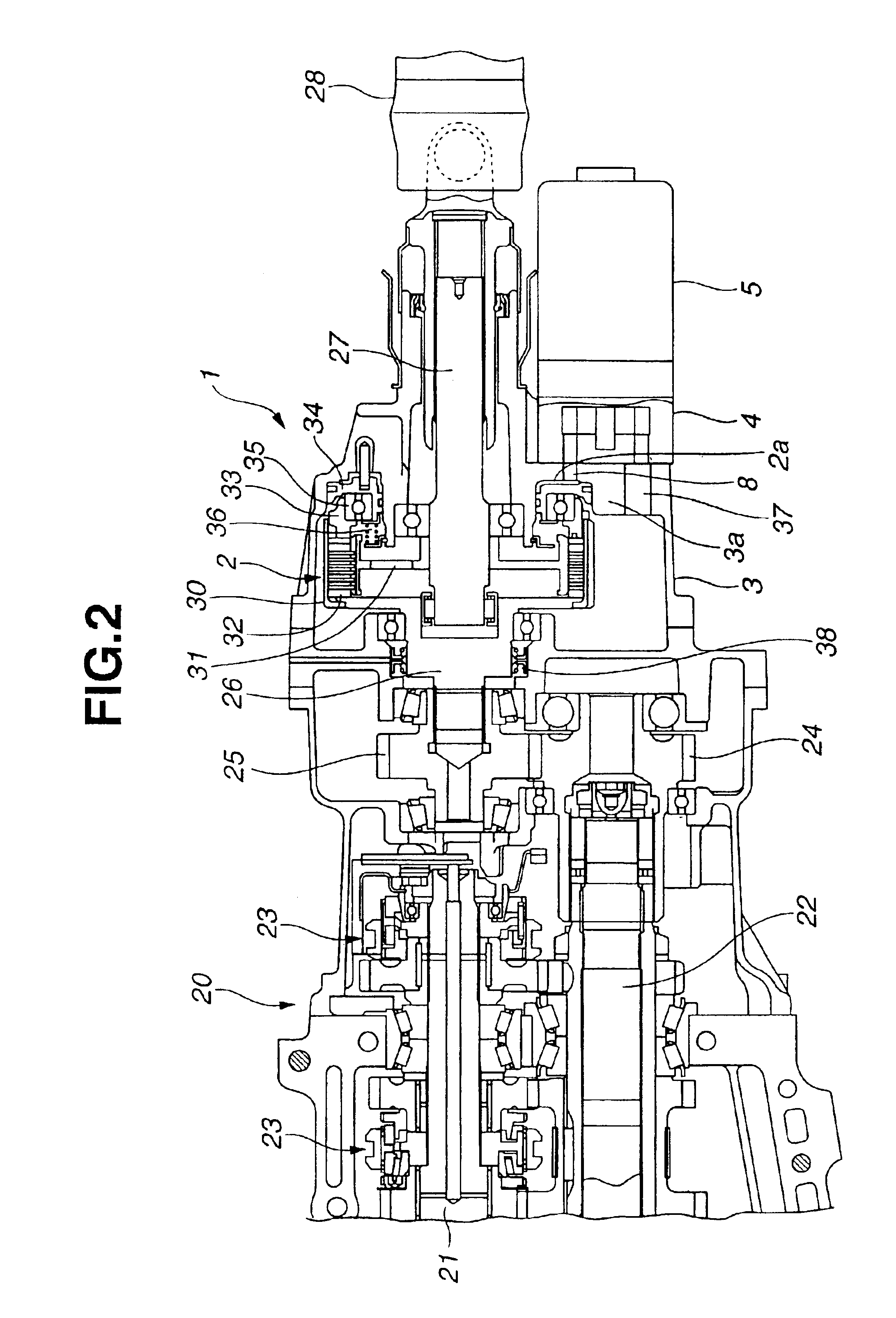
FIG. 1 schematically illustrates the structure of an electronic controlled coupling 1 provided in a power transmission system used for a vehicle. The electronic controlled coupling 1 includes a wet-type multiple disc clutch 2, a coupling case 3, an oil pump 4, an electric motor 5 (hereinafter, referred to as a motor 5), a motor driver 6, and an electric control unit 7 (hereinafter, referred to as an ECU 7), and these are integrated together. The wet-type multiple disc clutch 2 transmits driving torque by contacting surfaces of a plurality of alternately deposited driving plates and driven plates. The coupling case 3 accommodates the wet-type multiple disc clutch 2 and contains oil therein. The oil pump 4 is mounted to the coupling case 3, and sucks and pressurizes the oil to directly supply it to the wet-type multiple disc clutch 2. The motor 5 drives the oil pump 4, the motor driver 6 drives the motor 5, and the ECU 7 controls the motor driver 6. The coupling case 3 contains the oi...

second embodiment

An electronic controlled coupling according to a second embodiment of the present invention will now be described. Similar components as in the first embodiment are referred to with the same reference numerals, and the descriptions of those similar components will not be repeated here.

Referring to FIG. 5, an electronic controlled coupling 50 includes a cooling oil passage 51 for supplying cooling oil in order to effectively cool the wet-type multiple disc clutch 2. The cooling oil passage 51 branches off from the midstream of the supply passage 8 for supplying hydraulic pressure. Accordingly, the wet-type multiple disc clutch 2 is forcibly cooled by the oil from the cooling oil passage 51. The cooling oil passage 51 has an orifice 52 in the middle thereof, so that the amount of the oil for forcibly cooling the wet-type multiple disc clutch 2 is limited to the minimum necessary. The orifice 52 is not necessarily provided. If the minimum amount of the cooling oil required for cooling ...


PUM


Abstract

An electronic controlled coupling including a wet-type multiple disc clutch, a coupling case, a hydraulic chamber, an oil pump, an electric motor, an electric control unit, and a supply passage for supplying hydraulic pressure. The coupling case accommodates the wet-type multiple disc clutch and contains oil. The oil pump driven by the electric motor is connected to the coupling case. The outlet of the oil pump is connected to the hydraulic chamber of the wet-type multiple disc clutch with the supply passage therebetween. The electric control unit controls the speed of rotation of the electric motor through a motor driver so that the pump discharge pressure is equal to an operating pressure required for the wet-type multiple disc clutch. The electronic controlled coupling performs a complete coupling mechanism increasing the durability as a coupling and a compact and simple structure enhancing the flexibility in designing.

Description

The disclosure of Japanese Patent Application No. 2002-174811 filed on Jun. 14, 2002, and Japanese Patent Application No. 2002-174812 filed on Jun. 14, 2002 including the specifications, drawings and abstracts is incorporated herein by reference in its entirety.BACKGROUND OF THE INVENTION1. Field of the InventionThe present invention relates to electronic controlled couplings for transmitting torque with a wet-type multiple disc clutch engageable by hydraulic pressure.2. Description of the Related ArtA technology is known as a power transmission system used for four-wheel drive vehicles in which a coupling mechanism, such as a multiple disc clutch or a viscous coupling, continuously controls a driving force to be distributed to the rear wheels. In particular, four-wheel drive vehicles equipped with an automatic transmission can utilize a hydraulic power source of the automatic transmission; hence, many four-wheel drive vehicles of this, type use a hydraulic wet-type multiple disc cl...

Claims


Application Information

Patent Timeline
IPC IPC(8): F16D25/06F16D48/00F16D25/0638F16D48/02F16D48/06F16D28/00
CPCF16D25/0638F16D25/14F16D48/064F16D48/02F16D2500/1024
Inventor SAKATA, TAKATOSHIYOSHINAMI, KOUJIKANAZAWA, KAZUOMURAKAMI, MAMORU
Owner KOYO SEIKO CO LTD
Why Eureka
Try Eureka