V/STOL biplane aircraft

a biplane aircraft and aircraft technology, applied in the direction of vertical landing/take-off aircraft, aircraft navigation control, transportation and packaging, etc., can solve the problems of low airflow velocity of ducted fan outlet, poor flight stability characteristics, and high initial and maintenance costs of gyrocopters with prerotors. , to achieve the effect of reducing the airflow velocity of the ducted fan outlet and reducing the load of the disk

Inactive Publication Date: 2005-02-01
CHURCHMAN CHARLES GILPIN
View PDF33 Cites 52 Cited by
  • Summary
  • Abstract
  • Description
  • Claims
  • Application Information

AI Technical Summary

Benefits of technology

This invention provides for an exbedded, rather than an imbedded ducted fan to provide vertical lift. In this case the term “exbedded” indicates that the ducted fan rotor diameter extends beyond the outside diameter of the fuselage into the wings of the jyrodyne. The wings are integrated with the exterior edges of the ducted fan inlet shroud for the top wing, with a larger central and circular cutout for the bottom wing. This innovation allows the disk loading to be reduced to a value not much higher than a helicopter disk loading, thus reducing the ducted fan outlet airflow velocity to in the neighborhood of 80 mph.

Problems solved by technology

Their advantage in vertical lift capability is offset by their poor flight stability characteristics, and very high initial and maintenance costs.
Gyrocopters with prerotors do not have hovering capability in a loitering mode.
Due to the need for redundancy in case of a single engine failure, complex crossover shafting is required.
VTOL aircraft using ducted fans have been the most commonly developed prototype, but with little success.
While the ducted fan provides greater lift than a simple unducted propeller, the drag produced by the duct shroud in forward flight at speeds over 150 mph has greatly limited the success of this type of VTOL aircraft.
There are numerous fan-in-wing configurations, which have been patented, but none has proved to be successful.
The primary problem has been the high required disc loading causing high exhaust velocities.

Method used


Image

  • V/STOL biplane aircraft
  • V/STOL biplane aircraft
  • V/STOL biplane aircraft

Examples


Embodiment Construction

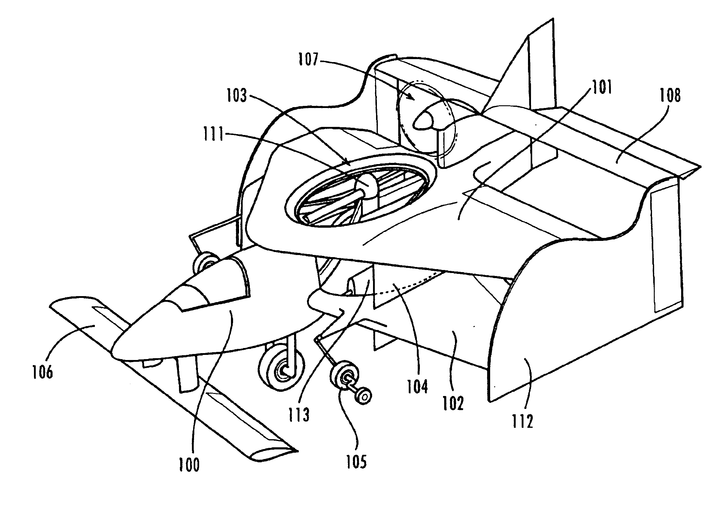
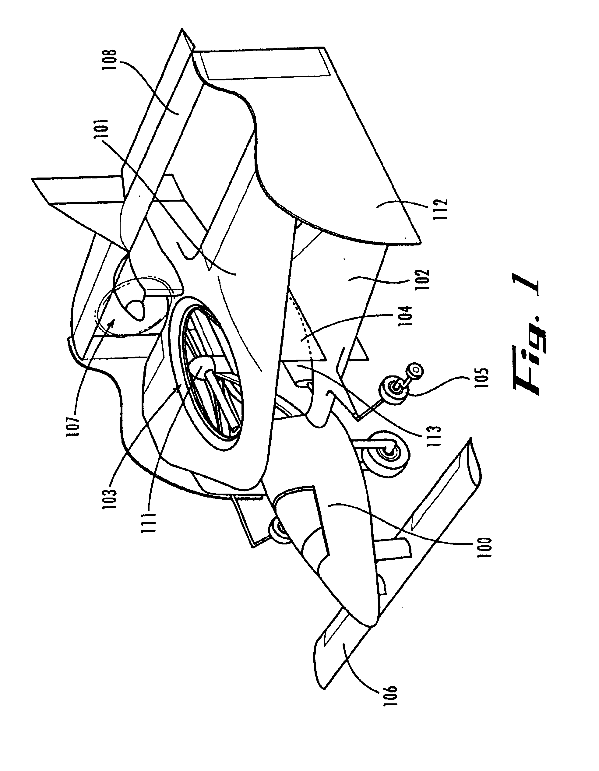
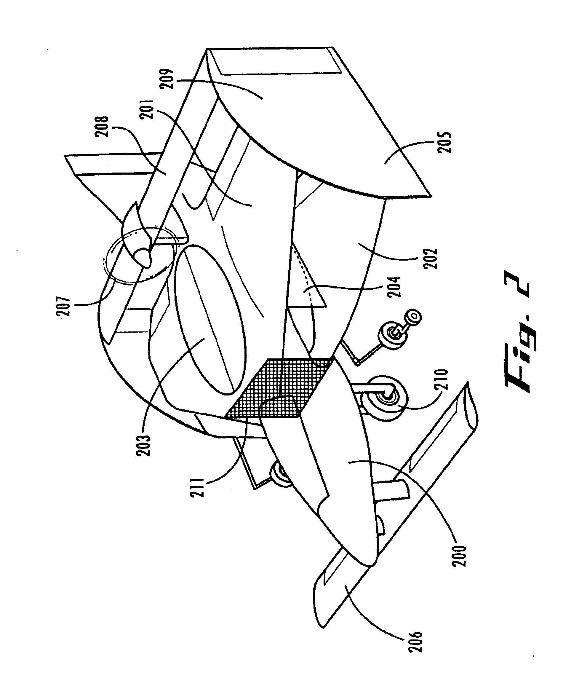
Referring to FIG. 2, the fuselage, 200, consists of three distinct sections. These are the front fuselage section, the middle fuselage section and the rear fuselage section. These three sections are indicated as 1 for the front fuselage section, 2 for the middle fuselage section and 3 for the rear fuselage section.

Weight and Balance Considerations

FIG. 3 illustrates a side view of another version of said jyrodyne aircraft, with the center of gravity vector depicted by arrow 4, at a position directly below the center of combined wing lift from the two biplane wings, arrow 8, which is called the jyrodyne center of lift. Said vector at arrow 4, also resides at the same longitudinal position as the ducted fan rotor axis. In stable hover mode, this point also resides at the jyrodyne center of gravity. Thus, this vendor resides at the combined location of the jyrodyne center or lift and gravity, called the jyrodyne center of lift / gravity. The ducted fan rotor hub is illustrated just below ...


PUM


Abstract

The present invention is a 2 passenger aircraft capable of vertical and conventional takeoffs and landings, called a jyrodyne. The jyrodyne comprises a central fuselage with biplane-type wings arranged in a negative stagger arrangement, a horizontal ducted fan inlet shroud located at the center of gravity in the top biplane wing, a rotor mounted in the shroud, outrigger wing support landing gear, a forward mounted canard wing and passenger compartment, a multiple vane-type air deflector system for control and stability in VTOL mode, a separate tractor propulsion system for forward flight, and a full-span T-tail. Wingtip extensions on the two main wings extend aft to attach to the T-tail. The powerplants consist of two four cylinder two-stroke reciprocating internal combustion engines. Power from the engines is distributed between the ducted fan and tractor propeller through the use of a drivetrain incorporating two pneumatic clutches, controlled by an automotive style footpedal to the left of the rudder pedals. When depressed, power is transmitted to the ducted fan for vertical lift. When released, power is transmitted to the tractor propeller for forward flight. The aircraft can also takeoff and land in the conventional manner with a much larger payload, and is easily converted to amphibious usage. Landing gear is a bicycle arrangement with outriggers. The aircraft combines twin engines, heavy-duty landing gear, controlled-collapse crashworthy seats with a low stall speed and high resistance to stalls to eliminate any region of the flight regime where an engine or drivetrain failure could cause an uncontrollable crash.

Description

FIELD OF THE INVENTIONThis invention relates to non-rotary wing vertical and short take-off and landing (V / STOL) passenger aircraft. Class 244 / 12.3 appears to be the most appropriate. More particularly, the present invention relates to a V / STOL aircraft in which the rotor plane of a single ducted fan is located horizontally inside the center of a conventional aircraft wing to provide vertical lift, with a fan diameter much greater than the fuselage width of said aircraft. An additional tractor or pusher propeller provides horizontal thrust for forward movement in the conventional manner, and is located above the rear part of the ducted fan. The aircraft utilizes two main wings in a negative staggered biplane arrangement, with an oversized stabilizer and elevator, and a canard mounted at the front of said aircraft. The ducted fan is mounted inside the top wing.The aircraft which is the subject of this invention is called a jyrodyne, to differentiate it from gyrodyne, a generic term: ...

Claims


Application Information

Patent Timeline
Patent Type & Authority Patents(United States)
IPC IPC(8): B64C29/00
CPCB64C29/0025
Inventor CHURCHMAN, CHARLES GILPIN
Owner CHURCHMAN CHARLES GILPIN
Why Eureka
Try Eureka