Method and apparatus for pleural drainage

a technology of pleural cavity and pleural tube, which is applied in the field of pleural cavity evacuation of liquids and air, can solve the problems of poor tube function or non-function, increase hospitalization time and pain, and reduce the medical benefits of the tub

Inactive Publication Date: 2005-02-01
WAGNER ROBERT B
View PDF28 Cites 192 Cited by
  • Summary
  • Abstract
  • Description
  • Claims
  • Application Information

AI Technical Summary

Benefits of technology

With respect to the aforementioned problems, it is therefore an object of the present invention to provide an apparatus and method for its use that overcomes the disadvantages of the prior art and is significantly more effective than previous devices or methods.

Problems solved by technology

However, passing a chest tube into a trauma patient's body so that the perforations at the distal end of the device are not partially blocked by a thoracic positioning between the lobes of a lung or having been placed between the chest wall and muscles, remains a challenge even to experienced emergency practitioners because it is a blind procedure.
A misplaced chest tube results in a poorly functional or nonfunctioning tube due to partial blockage of the tube and a corresponding increase in hospitalization time and pain.
Consequently, an improperly set chest tube reduces the medical benefits of the tube, possibly to the point where the risks are greater than the benefits of its use.
While various configurations of the above balloon catheter / cannula devices have been used in the prior art, including devices with multiple lumens and multiple balloons, each of which may be inflated with air or liquids pumped from the proximate end of the device, and placed with assistance of imaging systems, none of the above devices or methods of using balloons have been employed with a chest tube to accurately set the chest tube inside a patient's thoracic region or other cavity to increase the effectiveness of evacuation.

Method used


Image

  • Method and apparatus for pleural drainage
  • Method and apparatus for pleural drainage
  • Method and apparatus for pleural drainage

Examples


Embodiment Construction

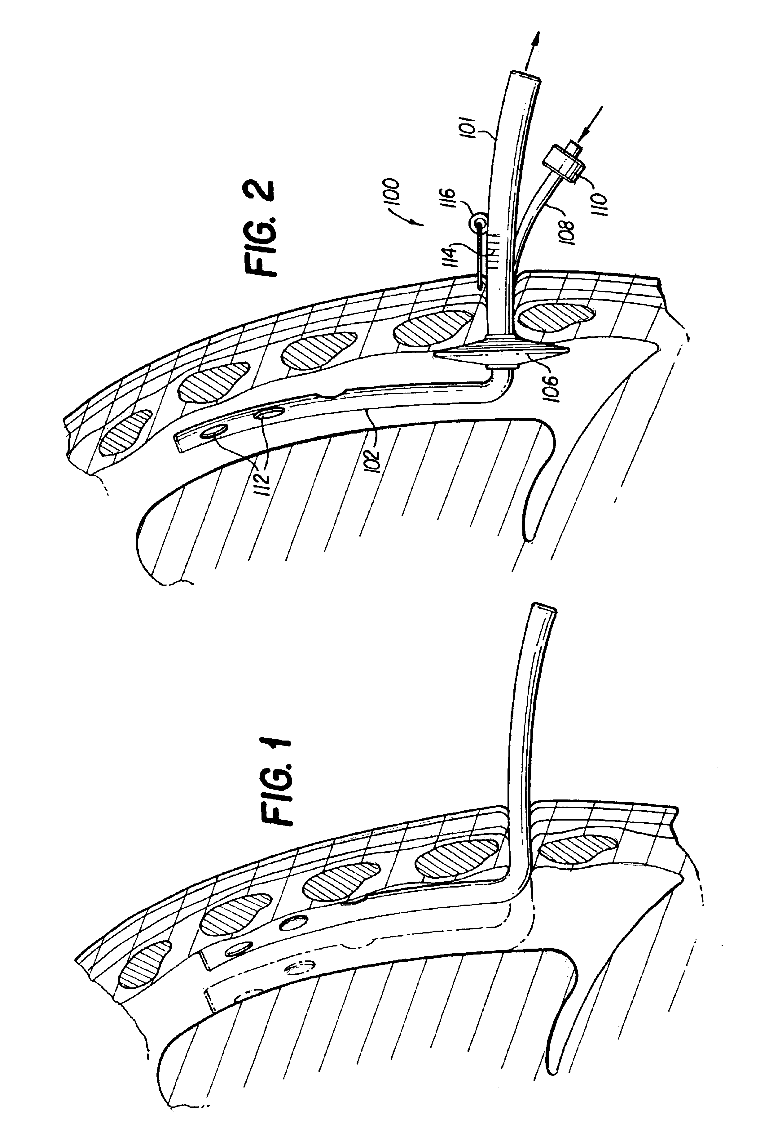
FIG. 1 is a schematic of a traditional chest tube and its placement inside the thoracic region of a patient through a percutaneous incision in the chest according to the prior art. As shown, the distal end of the chest tube, with its plurality of perforations for evacuating gases, liquids and solids, can easily rest against the structure of the ribs, if pulled forward, or pressed against the lungs, if pushed too far inward, reducing the volumetric flow rate of materials being evacuated. As shown in FIG. 1, a practitioner has a very small space in which set the chest tube to maximize the efficiency of the device.

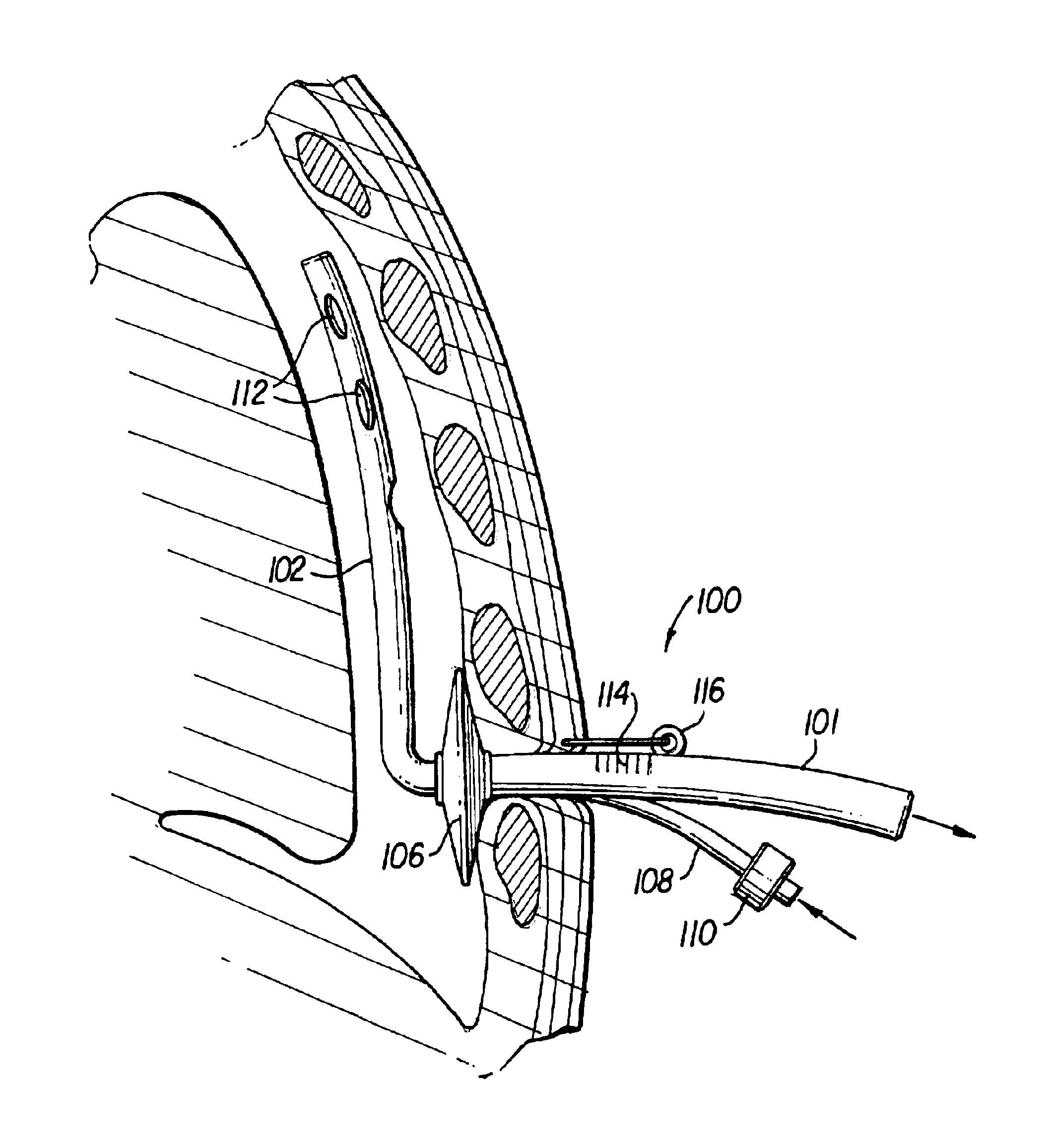
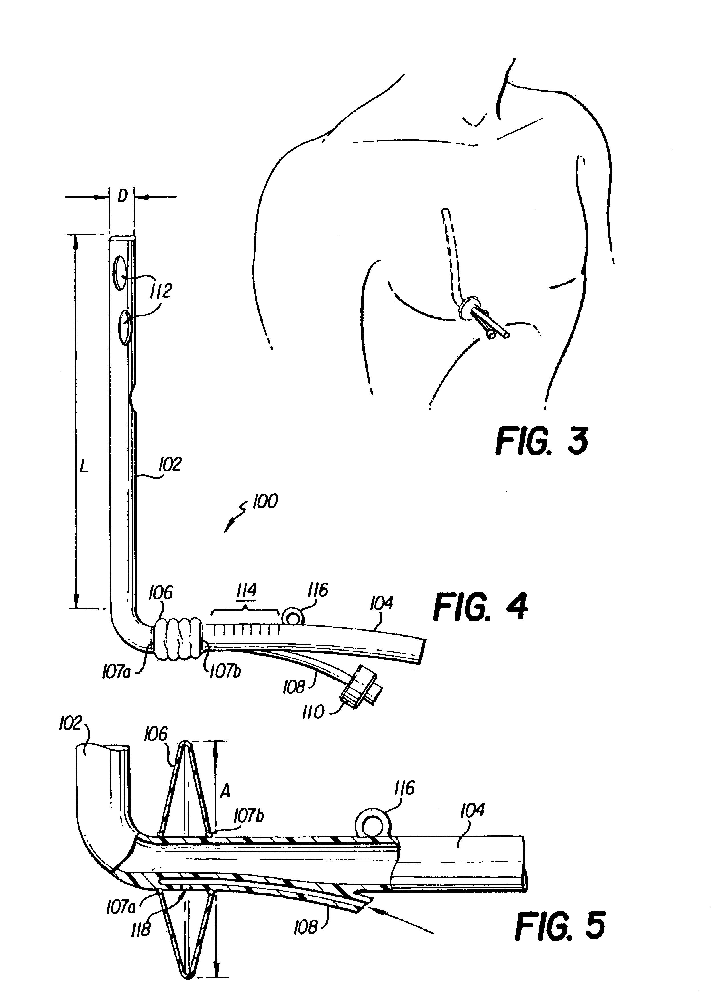
FIG. 2 is a schematic of a chest tube 100, manufactured in accordance with the present invention, that is placed inside the thoracic cavity of a patient through a percutaneous incision in the patient's chest. The chest tube 100 is generally L-shaped, having a distal section 102 for receiving fluid, a proximal section 104 for the carrying of the fluid outwardly from the chest....


PUM


Abstract

Apparatus and method for evacuating material from a body cavity are disclosed. An elongated tubular member constructed and arranged to be inserted through an aperture in a patient's chest is provided. The tubular member is generally L-shaped and has a distal section and a proximal section. The distal section includes a plurality of openings for receiving air and liquids from within the patient's body. The proximal section receives and discharges air and liquids to a receiver. The proximal section includes an expandable cuff for positioning the tubular member in the patient's chest for preventing the plurality of openings from being obstructed in whole or in part.

Description

BACKGROUND OF THE INVENTION1. Field of the InventionThe invention relates to the evacuation of liquids and air from the pleural cavity in mammals. In particular, this invention relates to a chest tube and method for rapidly and accurately setting the chest tube in a patient in a medical emergency or trauma setting such that the tube performance is not impeded when inserted.2. Background of the InventionThousands of cannulas or trocar catheters are inserted each year in patients suffering chest trauma brought on by incidents such as auto accidents, punctures and lung disease. These devices are used to evacuate air and liquids from the patient's pleural cavity, defined as that area of the human body between the neck and the diaphragm, partially encased by the ribs and containing the lungs. As is often the case in these situations, evacuation of materials is required immediately upon receiving a patient for treatment during an emergency and may be required for an extended period of tim...

Claims


Application Information

Patent Timeline
Patent Type & Authority Patents(United States)
IPC IPC(8): A61M27/00
CPCA61M27/00A61M2210/101A61M2025/0233
Inventor WAGNER, ROBERT B.
Owner WAGNER ROBERT B
Why Eureka
Try Eureka