Multibeam laser drilling apparatus

a laser drilling and multi-beam technology, applied in the direction of optical elements, manufacturing tools, instruments, etc., can solve the problems of inability to increase the size of the first galvanometer mirror system, and the inability to increase the deflection angle to a large valu

Active Publication Date: 2005-02-01
HITACHI SEIKO LTD
View PDF11 Cites 102 Cited by
  • Summary
  • Abstract
  • Description
  • Claims
  • Application Information

AI Technical Summary

Benefits of technology

[0011]By adopting a conventional optical system using a galvanometer-mirror system, the galvanometer mirror can be located near to the fθ lens for the first laser beam, and accordingly, occurrence of the telecentric error can be prevented. Further, as to the second laser beam, the telecentric error can be suppressed by decreasing angles of the second galvanometer-mirror system to small values. However, since the response speed becomes slow, the size of the first galvanometer-mirror system cannot be increased, and further, if the deflection angle of the second beam becomes larger, causing such a problem that the laser beam misses the first galvanometer-mirror system, the deflection angle cannot be increased to a large value. Thus, the distance between a converging position of the first laser beam and a converging position of the second laser beam has to be decreased. However, drilling processes of these years require to set intervals of micro-holes to values not greater than 1.5 mm, and accordingly, the distance problem does not affect the drilling process.
[0013]In the case of the laser head as stated above, it is similar to the laser head as in the above-mentioned first aspect of the present invention as to the first laser beam, but as to the second laser beam, the second galvanometer-mirror system can be located close to the first galvanometer-mirror system so that deflection angles of the second laser beam can be increased to larger values, thereby it is possible to increase the distance between the converged positions of the first laser beam and the second laser beam.
[0016]Further, with this laser head, the second S-polarized laser beam is reflected by the second fixed mirror, and is deflected by the second galvanometer-mirror system which is configured such that the direction of the drive shaft of the galvanometer mirror for the X-axial direction is coincident with the direction of the drive shaft of the galvanometer mirror for the X-axial direction of the first galvanometer-mirror system, while the direction of the drive shaft of the galvanometer mirror for the Y-axial direction is made orthogonal to the direction of the drive shaft of the galvanometer mirror for the Y-axial direction of the first galvanometer-mirror system, spatial interference caused by the mirror drive motors can be reduced, and accordingly, the galvanometer mirrors can be placed close to one another, thereby it is possible to further reduce telecentric errors caused by the fθ lens.

Problems solved by technology

However, since the response speed becomes slow, the size of the first galvanometer-mirror system cannot be increased, and further, if the deflection angle of the second beam becomes larger, causing such a problem that the laser beam misses the first galvanometer-mirror system, the deflection angle cannot be increased to a large value.

Method used


Image

  • Multibeam laser drilling apparatus
  • Multibeam laser drilling apparatus
  • Multibeam laser drilling apparatus

Examples


embodiment 1

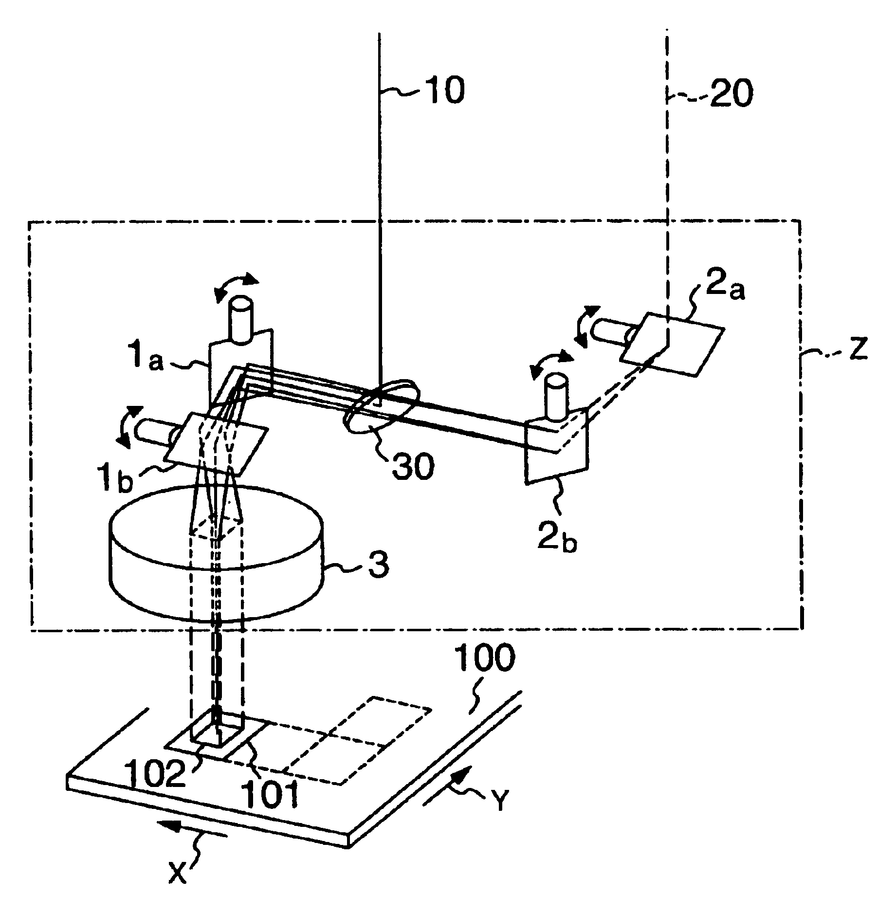
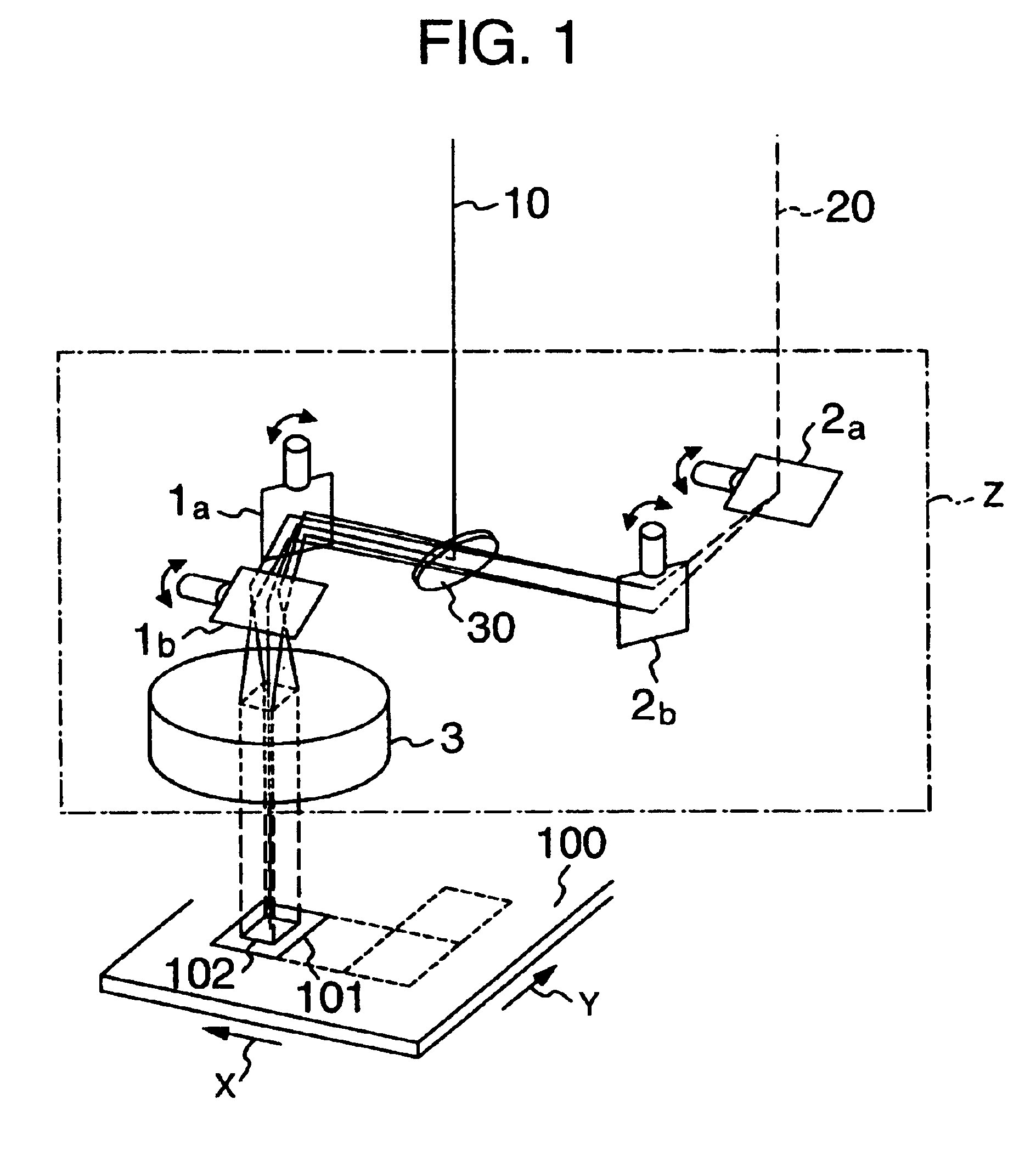
[0029]Referring to FIGS. 1 and 2 which show a laser head optical system in the present invention, there are shown a first galvanometer-mirror system composed of galvanometer mirrors 1a, 1b, a second galvanometer-mirror system composed of galvanometer mirrors 2a, 2b, an fθ lens 3, an S-polarized first laser beam 10, a P-polarized second laser beam 20, a printed circuit board 100 as a workpiece, a positioning range 101 of the first laser beam, a positioning range 102 of the second laser beam, and a laser head Z. The positioning range of the first laser beam 10 will be explained with reference to FIG. 2. Since the first laser beam 10 is S-polarized, after it is reflected by a polarized beam mixer 30, it is deflected by the first galvanometer-mirror system 1a, 1b and is then incident upon the fθ lens 3 so as to be positioned and converged in the range 101 on the printed circuit board 100 as a workpiece and is converged, similar to the conventional one. Next, the positioning range 102 of...

embodiment 4

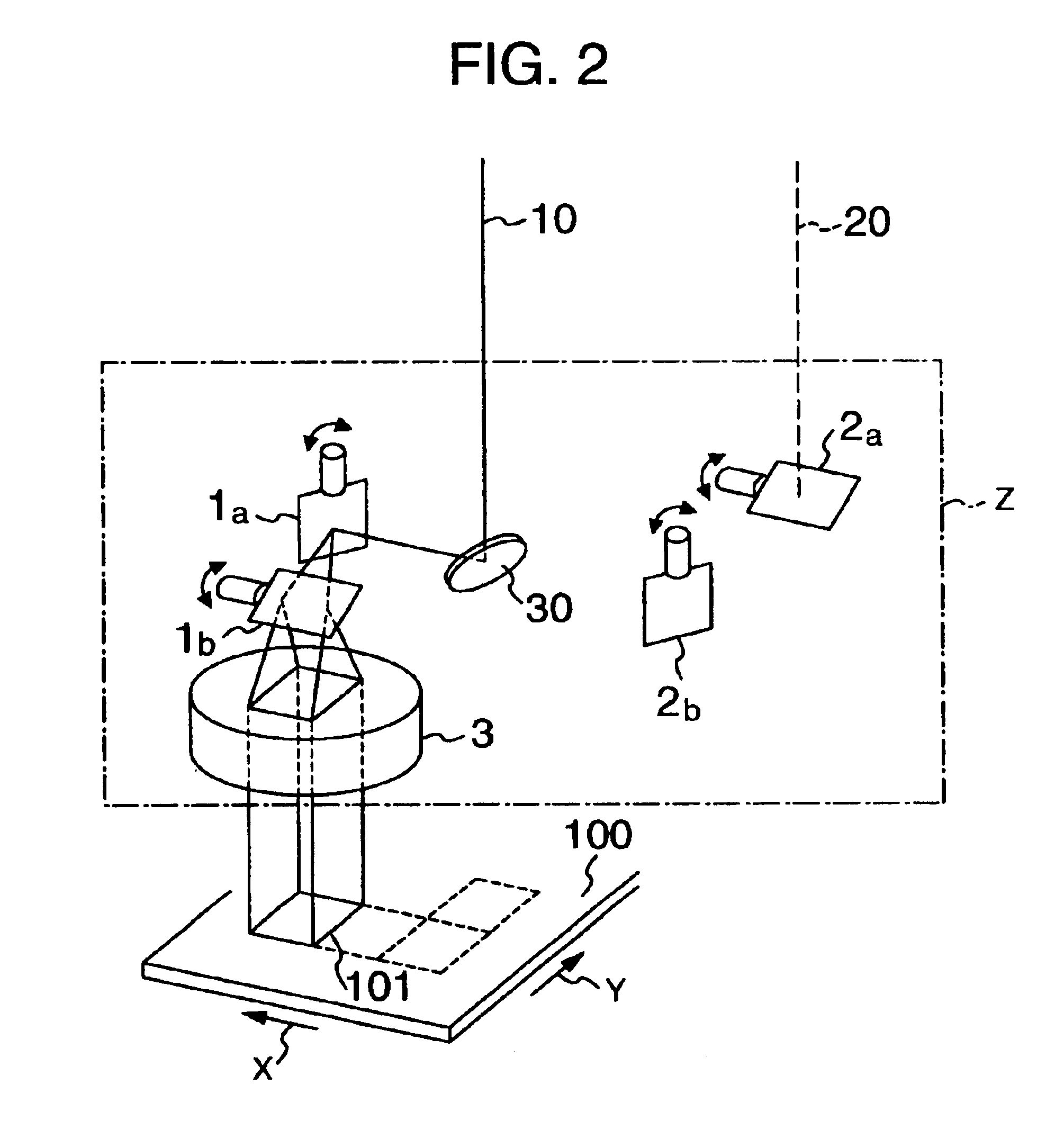
[0033]Referring to FIG. 4 which shows a laser head optical system in the present invention, there are shown a first galvanometer-mirror system composed of galvanometer mirrors 1a, 1b, a second galvanometer-mirror system composed of galvanometer mirrors 2a, 2b, an fθ lens 3, fixed mirrors 4 and 5, an S-polarized second laser beam 10, a P-polarized first laser beam 20, a printed circuit board 100 as a workpiece, a positioning range 101 of the first laser beam, a positioning range 102 of the second laser beam, and a laser head Z. In this figure, the positioning range 102 corresponds to a movable range of the second laser beam when the first galvanometer-mirror system 1a, 1b is fixed, similar to FIG. 1. The second laser beam 10 in this embodiment is reflected by the fixed mirror 5, and is deflected by the second galvanometer-mirror system, and since it is S-polarized, it is reflected by the polarized beam mixer 30, and is deflected by the first galvanometer-mirror system 1a, 1b. Then, i...


PUM

PropertyMeasurementUnit
deflection angleaaaaaaaaaa
diameteraaaaaaaaaa
distanceaaaaaaaaaa

Abstract

Provided is a multi-beam laser drilling apparatus for drilling a workpiece, simultaneously at two positions while telecentric errors are suppressed, in which a conventional optical system in which galvanometer mirrors are used for a first laser beam, and a galvanometer-mirror system is located close to an fθ lens in order to prevent occurrence of telecentric error. A second laser beam which has been deflected by a second galvanometer-mirror system, transmits through a polarized beam mixers and is incident upon the first galvanometer-mirror system and the fθ lens, and accordingly, the workpiece is drilled simultaneously at two positions with the use of both first and second laser beams.

Description

BACKGROUND OF THE INVENTION[0002]The present invention relates to a high speed laser drilling apparatus using a plurality of laser beams.[0003]A printed circuit board used in a mobile telephone or the like has been smaller year after year. Further, the number of holes drilled in a circuit board has been increased, that is, not less than 3,000 of micro-sized holes are formed therein.[0004]In order to form micro-sized holes in a printed circuit board, a micro-hole drilling process using a laser beam is used. As to this process, as disclosed in JP-A-63-147138 (Refer to in particular to FIGS. 1 and 2), a laser drilling process in which two mirrors (which will be hereinbelow referred to as “galvanometer-mirror system”) that are rotated around two orthogonal axes, respectively, and an fθ lens are used for converging light and positioning the converging point, has been prosperously used. As the number of micro-sized holes is increased, there has been increased demands of to increase the dr...

Claims


Application Information

Patent Timeline
Patent Type & Authority Patents(United States)
IPC IPC(8): B23K26/067B23K26/00B23K26/38B23K26/06H05K3/00G02B26/10B23K26/064B23K26/382B23K101/42
CPCB23K26/0639B23K26/0643B23K26/0648B23K26/067B23K26/4025B23K26/381H05K3/0026B23K26/0807B23K26/0673B23K26/064B23K26/082B23K26/382B23K2103/50B23K26/04
Inventor ARAI, KUNIOSUZUKI, KENJI
Owner HITACHI SEIKO LTD
Why Eureka
Try Eureka