Enhanced efficiency LDMOS based feed forward amplifier

Active Publication Date: 2005-02-01
INTEL CORP
View PDF35 Cites 4 Cited by
  • Summary
  • Abstract
  • Description
  • Claims
  • Application Information

AI Technical Summary

Benefits of technology

Further features and advantages will be appreciated by review of the following detailed description of the invention.

Problems solved by technology

Both these requirements are critical for modern wireless communication systems but it is increasingly difficult to provide both.
This is due primarily to the bandwidth requirements of modern wireless communication systems which are placing increasing demands on amplifier linearity.
In order to obtain higher efficiency from the output stage LDMOS (Laterally Diffused Metal Oxide Semiconductor) devices in an amplifier, they must be biased towards lower class AB or in class B. However, when biased in this mode, considerable gain expansion occurs, especially at lower power outputs.
This gain expansion also creates a substantial amount of small signal intermodulation distortion products (SSIMDs).
This is contradictory to the fundamental concept of feed forward amplifier operation and is inherently difficult to deal with.
These IMD products in turn cause the error amplifier to draw substantially higher current to compensate so that any efficiency improvement is lost at the system level.
As a result, an attempt to increase efficiency by biasing the amplifier devices at lower class AB or in class B is frustrated in this manner.

Method used


Image

  • Enhanced efficiency LDMOS based feed forward amplifier
  • Enhanced efficiency LDMOS based feed forward amplifier
  • Enhanced efficiency LDMOS based feed forward amplifier

Examples


Embodiment Construction

The present invention provides a feed forward amplifier and signal linearization method which substantially eliminates all the above mentioned problems and achieves better overall system efficiency even when the main and / or error amplifier are biased in a substantially lower bias class for higher efficiency.

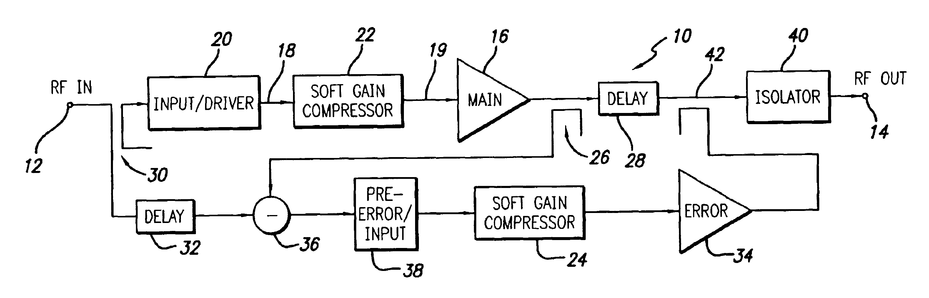
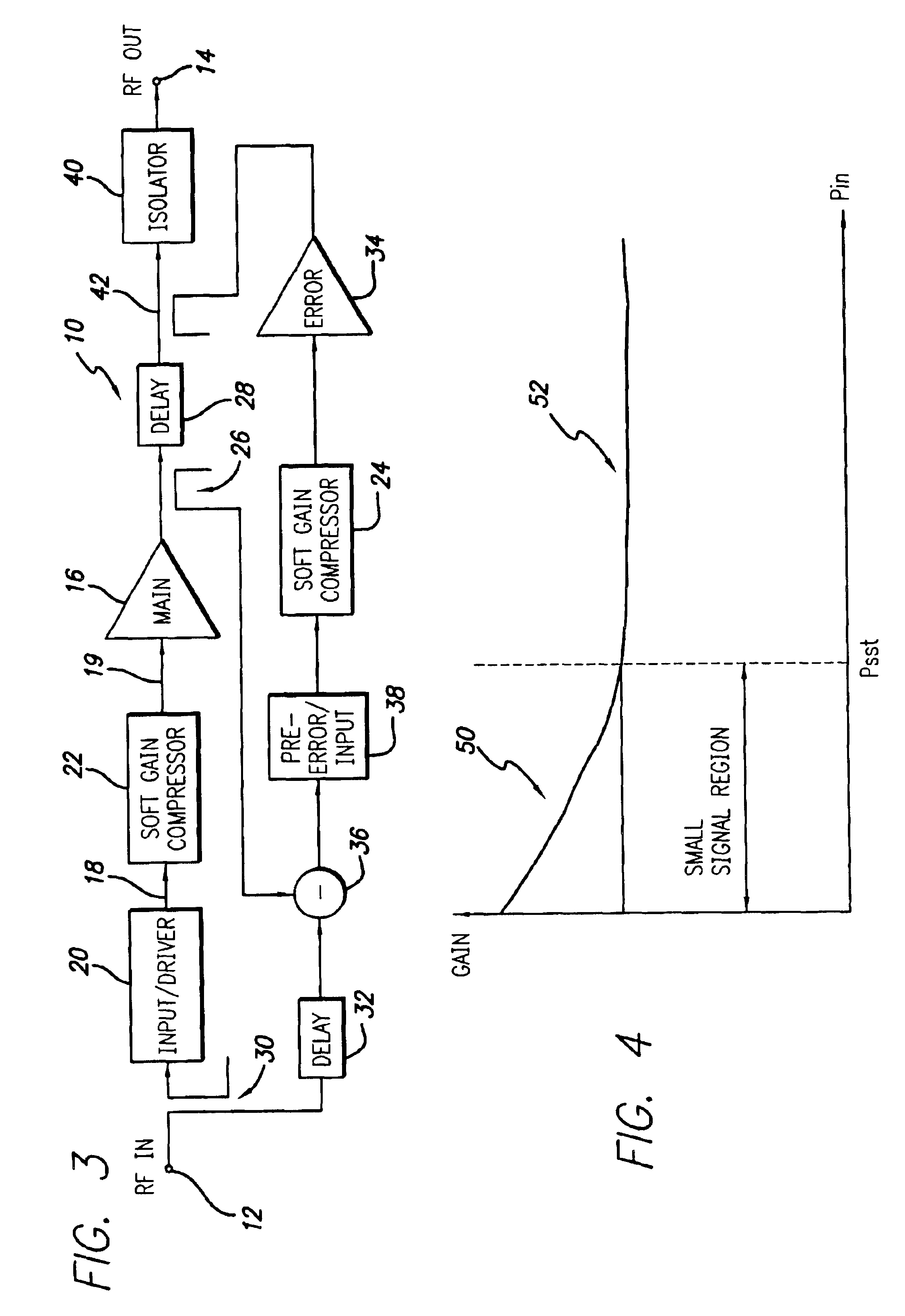
Referring to FIG. 3 a block diagram of a preferred embodiment of a feed forward power amplifier in accordance with the invention is illustrated. Although a feed forward amplifier is illustrated it should be appreciated that the present invention may also be implemented in other amplifier designs. The feed forward amplifier 10 includes an input 12 which receives an input RF signal to be amplified and an output 14 which outputs the amplified RF signal. The input RF signal is split into a main amplifier signal path and an error amplifier signal path at input coupler 30 in accordance with well known feed forward amplifier design.

The main amplifier signal path includes main amplifier ...


PUM


Abstract

A feed forward amplifier employing high efficiency main and / or error amplifiers with amplifier devices biased in a lower bias class. Small signal nonlinearities in the gain response of the amplifier devices are compensated by a small signal gain adjustment circuit. The resulting gain response is substantially linear over the entire usable range of RF input power.

Description

BACKGROUND OF THE INVENTION1. Field of the InventionThe present invention relates in general to RF power amplifiers and methods of amplifying an RF signal. More specifically, the present invention relates to feed forward power amplifiers and related methods.2. Description of the Prior Art and Related InformationThe two primary goals of RF power amplifier design are linearity over the range of power operation and efficiency. Linearity is simply the ability to amplify without distortion while efficiency is the ability to convert DC to RF energy with minimal wasted power and heat generation. Both these requirements are critical for modern wireless communication systems but it is increasingly difficult to provide both. This is due primarily to the bandwidth requirements of modern wireless communication systems which are placing increasing demands on amplifier linearity. As a practical matter the only way to provide the desired linearity has been to employ very large amplifiers operating...

Claims


Application Information

Patent Timeline
IPC IPC(8): H03F1/02H03F1/32H03F1/26
CPCH03F1/0266H03F1/26H03F1/3229H03F1/3247H03F1/3223H03F2200/102H03F1/32H03F1/00
Inventor GURVICH, MARKMASLENNIKOV, NIKOLAI
Owner INTEL CORP
Why Eureka
Try Eureka