Energy recovery circuit for driving a capacitive load

a capacitive load and energy recovery technology, applied in the direction of electronic switching, pulse technique, instruments, etc., can solve the problems of affecting the efficiency of the panel, generating electrical noise, slow current decay, etc., and achieve the effect of reducing the number of times of rise and fall

Inactive Publication Date: 2005-02-01
PANASONIC CORP
View PDF15 Cites 24 Cited by
  • Summary
  • Abstract
  • Description
  • Claims
  • Application Information

AI Technical Summary

Benefits of technology

It is a further object of the present invention to provide such a circuit that recovers energy when employed to drive a plasma display panel.
Another embodiment of the invention provides a slower rise time with a longer fall time.

Problems solved by technology

All of the aforesaid components are low loss components so the current decay is slow.
Nevertheless, the turn on timing of the pull down driver influences the efficiency of the panel and the generation of electrical noise.

Method used


Image

  • Energy recovery circuit for driving a capacitive load
  • Energy recovery circuit for driving a capacitive load
  • Energy recovery circuit for driving a capacitive load

Examples


Embodiment Construction

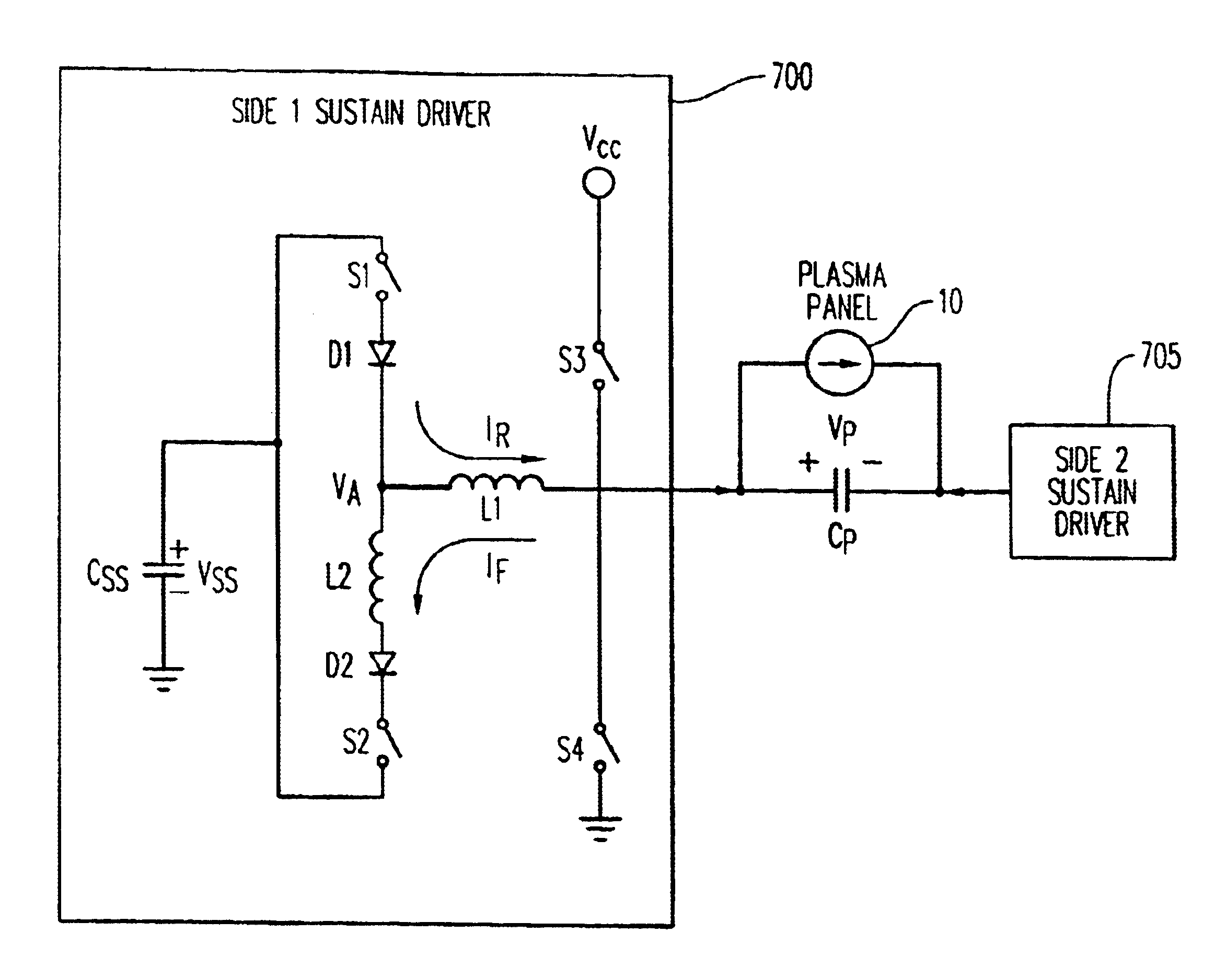
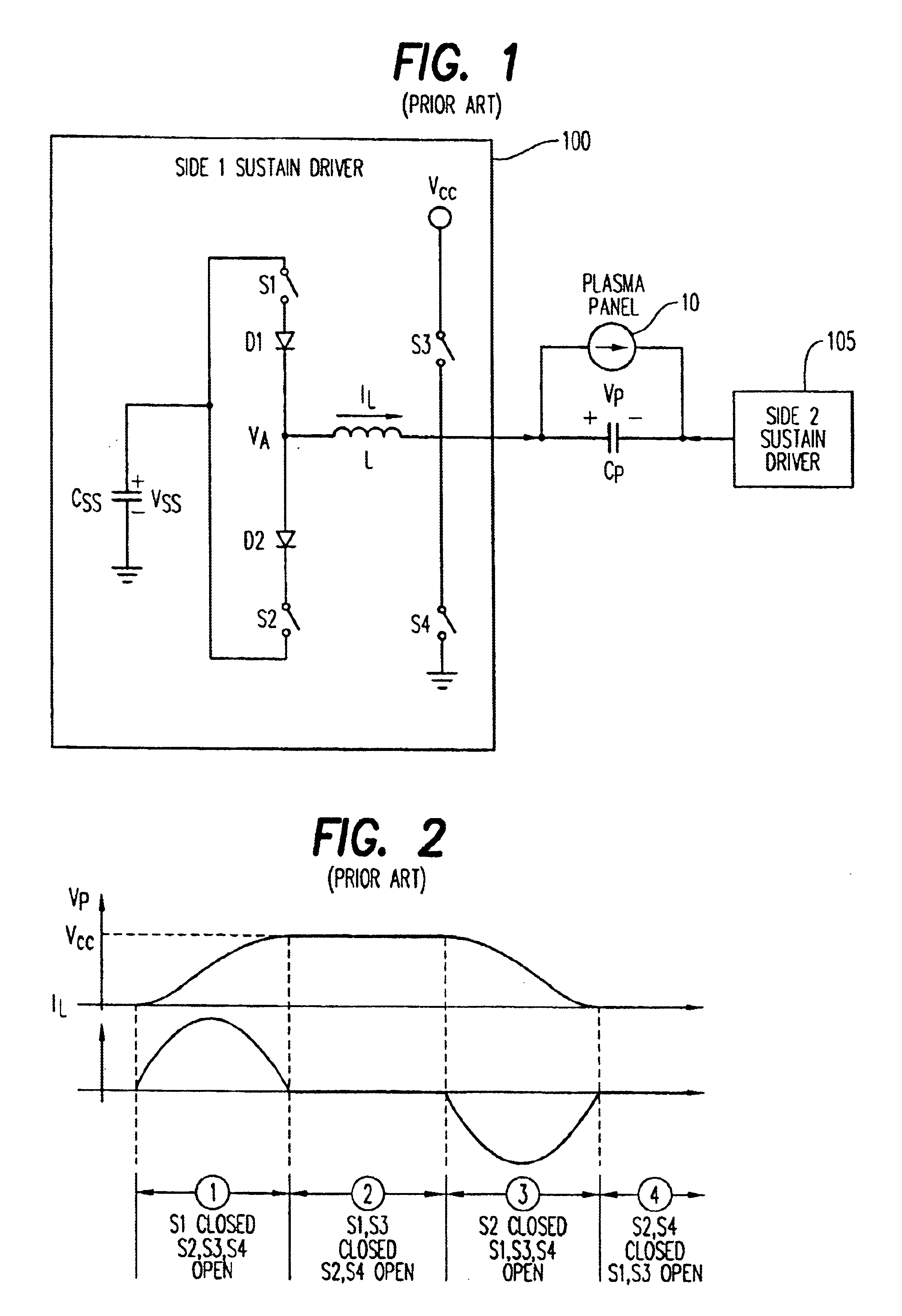
FIG. 7 is an idealized schematic of a sustain driver 700, in accordance with the present invention, for a plasma display panel. The principal components of sustain driver 700 are four switching devices, i.e., switches, S1, S2, S3 and S4 and two inductive components, i.e., inductors L1 and L2. A control signal is provided from a source (not shown in FIG. 7) to control switches S1-S4 so that sustain driver 700 progresses through four successive switching states, i.e., State 1, State 2, State 3 and State 4. Sustain driver 700 outputs a sustain pulse, which is represented as a panel voltage Vp.

L1 influences both a transition time of a rising edge of the sustain pulse and a transition time of a falling edge of the sustain pulse. L1 and L2 influence the transition time of the falling edge so that the rising edge and the falling edge are asymmetrical. A first current flows through L1 to produce the rising edge, and a second current flows through both of L1 and L2 to produce the falling edg...


PUM


Abstract

A circuit for providing a pulse to drive a capacitive load comprises (a) a first inductive component that influences both a transition time of a rising edge of the pulse and a transition time of a falling edge of the pulse, and (b) a second inductive component that influences one of the transition time of the rising edge and the transition time of the falling edge so that the rising edge and the falling edge are asymmetrical.

Description

BACKGROUND OF THE INVENTION1. Field of the InventionThe present invention relates to a sustain signal driver circuit for a capacitive display panel and, more particularly, to a sustain signal driver circuit for minimizing power loss when driving a capacitive load.2. Description of the Prior ArtPlasma display panels (PDPs) are well known in the art and include a front plate with horizontal electrode pairs having a capacitance there between. The electrode pairs are covered by a glass dielectric layer and a magnesium oxide (MgO) layer. A back plate supports vertical barrier ribs and plural vertical column electrodes. The individual column electrodes are covered with red, green, or blue phosphors, as the case may be, to provide for a full color display. The front and rear plates are sealed together and the space there between is filled with an electrically dischargeable gas.A pixel is defined by an intersection of an electrode pair on the front plate and three column electrodes for red,...

Claims


Application Information

Patent Timeline
Patent Type & Authority Patents(United States)
IPC IPC(8): G09G3/28G09G3/20G09G3/296H03K17/687
CPCG09G3/2965G09G2310/0267G09G2330/06G09G2330/024G09G2310/0275G09G3/296
Inventor MARCOTTE, ROBERT G.
Owner PANASONIC CORP
Why Eureka
Try Eureka