
Single side band modulator

Inactive Publication Date: 2005-02-01
SYNERGY MICROWAVE CORP
View PDF13 Cites 19 Cited by
  • Summary
  • Abstract
  • Description
  • Claims
  • Application Information

AI Technical Summary

Benefits of technology

An aspect of the present invention is a single side band modulator comprising a quadrature hybrid for splitting a signal into a first split signal and a second split signal 90 degrees out of phase with the first split signal but otherwise identical, a first double balanced mixer for modulating the first split signal with a first modulating signal to form a first output signal, the first double balanced mixer having a first transformer, a first modulating signal input, and a first diode ring, wherein the first transformer electrically connects said first diode ring to said quadrature hybrid, a second double balanced mixer for modulating the second split signa

Problems solved by technology

Unwanted side band suppression and carrier rejection are important performance issues for such structures.

Method used


Image

  • Single side band modulator
  • Single side band modulator
  • Single side band modulator

Examples


Embodiment Construction

The invention is an implementation of a single side band (SSB) modulator, resulting in improved performance, reduced component count and subsequently reduced cost and size.

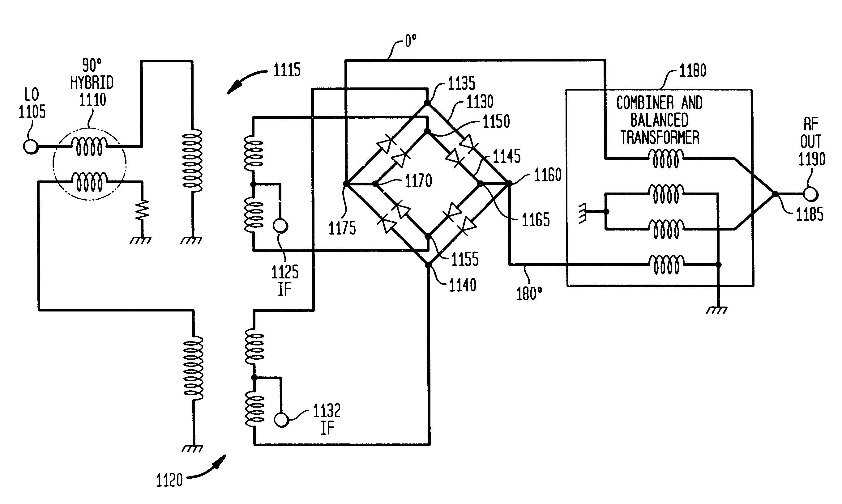
FIG. 11 is a circuit diagram of one embodiment of the present invention. At the LO port 1105 a local oscillator signal is applied. The 90 degree hybrid 1110 creates two signals in quadrature. In the LO side first transformer 1115 yields a 1:4 impedance change, as does the LO side second transformer 1120. First IF port 1125 and second IF port 1132 tap the secondary winding of the respective transformers. 90 degree phase shifted low frequency modulating signals are applied to the first and second IF ports 1125 and 1132. The outer schottky diode ring 1130 is connected in parallel to the second transformer 1120 at the points 1135 and 1140. The inner schottky diode ring 1145 is connected in parallel to the first transformer 1115 at the points 1150 and 1155. However, the outer schottky diode ring 1130 is not connected i...


PUM


Abstract

The present invention relates to a single side band modulator for splitting a signal into a first split signal and a second split signal 90 degrees out of phase with the first split signal. A first double balanced mixer modulates the first split signal and includes a transformer, a modulating signal input, and a first diode ring. The transformer connects the first diode ring to a quadrature hybrid. A second double balanced mixer modulates the second split signal and includes a transformer, a modulating signal input, and a second diode ring. The transformer of the second double balanced mixer connects the second diode ring to the quadrature hybrid. The first and second diode rings are connected in parallel and are connected to a third transformer which performs the function of a power combiner.

Description

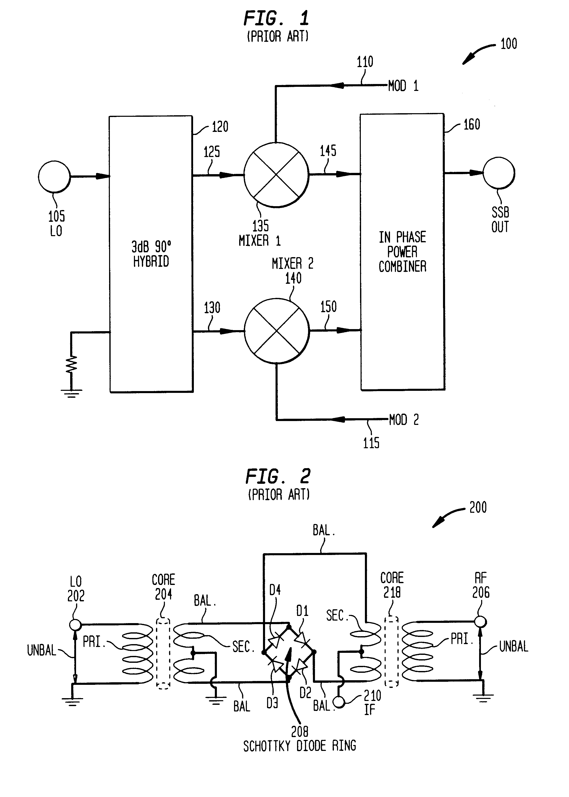
BACKGROUND OF THE INVENTIONSingle side band (SSB) modulators are used in many communication ECM systems. Most of these modern systems employ solid state modulators which have been designed using both active and passive components in a variety of circuit configurations. These configurations include single balanced structures and double balanced structures. Unwanted side band suppression and carrier rejection are important performance issues for such structures.One way of creating a single side band signal is the phase cancellation method. A low frequency (LF) signal, typically an information-bearing signal, is split into two identical but 90° phase shifted signals. The two low frequency signals are said to be in quadrature. A radio frequency carrier signal is provided by local oscillator (LO), and is also split into separate signals, so that the separate signals have a 90° phase shift relative to each other. One radio frequency carrier signal and one low frequency (LF) signal are com...

Claims


Application Information

Patent Timeline
IPC IPC(8): H03C1/00H03C1/60H03C1/52H03D7/14
CPCH03D7/1408
Inventor AHMED, VASEEM
Owner SYNERGY MICROWAVE CORP
Learn More