Lighting arrangement for automated optical inspection system

an optical inspection system and light arrangement technology, applied in the field of automatic optical inspection systems, can solve the problems of defective or passed boards, light emitting elements, light source types, etc., and achieve the effect of reducing the variation in beam intensity and reducing the size of the area

Inactive Publication Date: 2005-02-01
LANDREX TECH CO LTD
View PDF12 Cites 26 Cited by
  • Summary
  • Abstract
  • Description
  • Claims
  • Application Information

AI Technical Summary

Benefits of technology

In the preferred embodiments, the substrates are mounted along lines that radiate from a common point and the light emitting elements are mounted to focus their beams at an inspection area below this common point. Another feature of the preferred embodiments is that light emitting elements mounted further from the common have a narrower beam angle tha

Problems solved by technology

If they are not verified, the board is either labeled as defective or passed on for human inspection or additional testing.
However, these types of light sources had several drawbacks.
The drawback of annular lighting systems, though, is that the light emitting elements that are used to illuminate the inspection area from a low elevation angle are further from

Method used


Image

  • Lighting arrangement for automated optical inspection system
  • Lighting arrangement for automated optical inspection system
  • Lighting arrangement for automated optical inspection system

Examples


Embodiment Construction

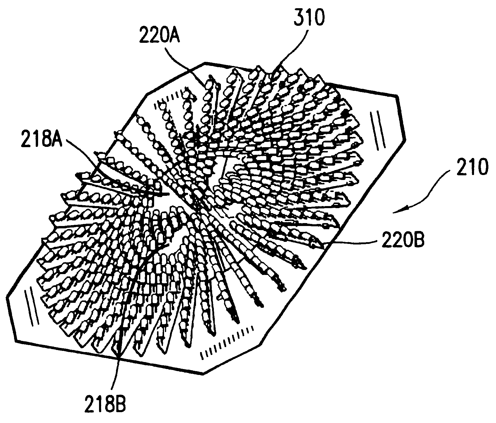
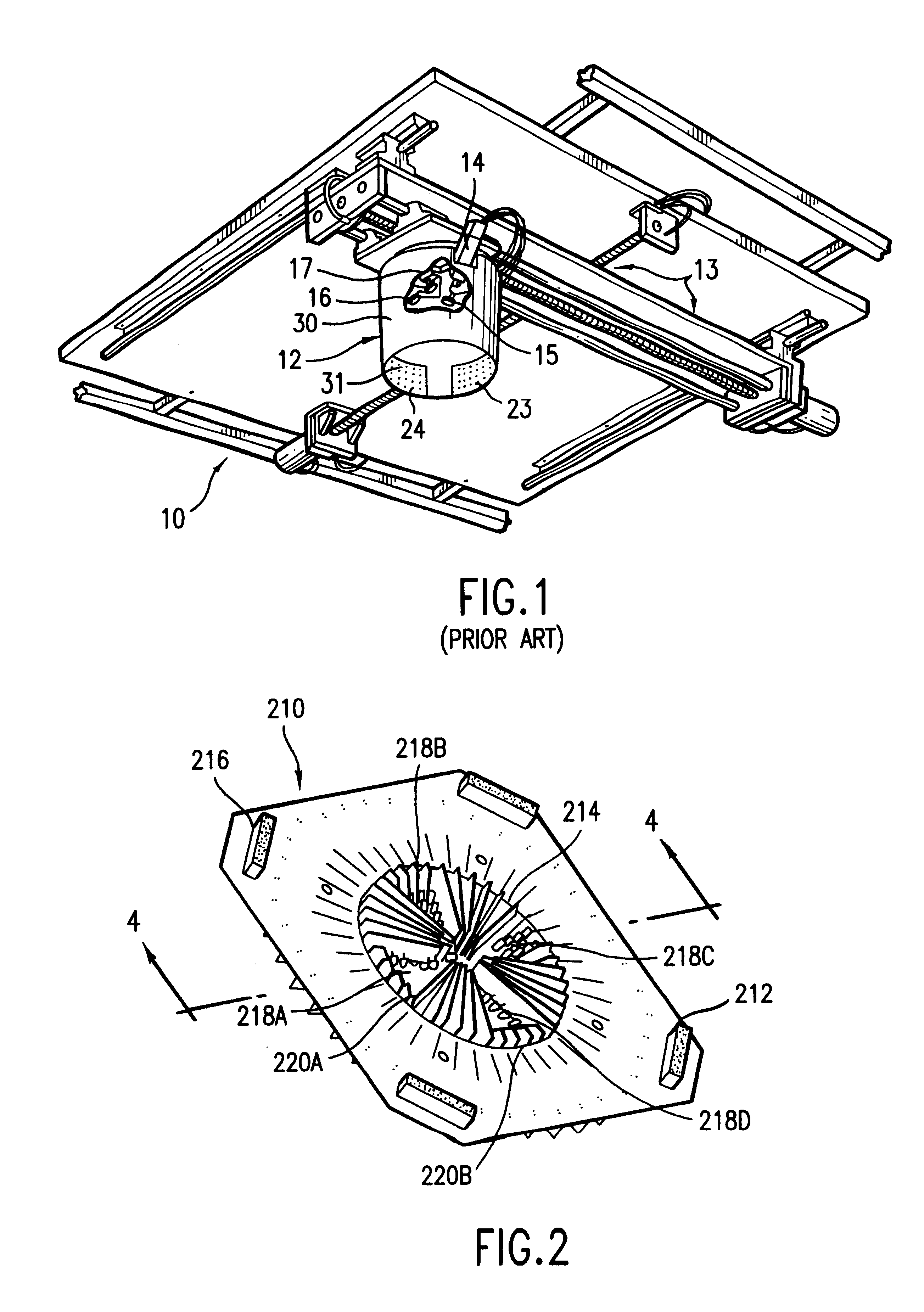
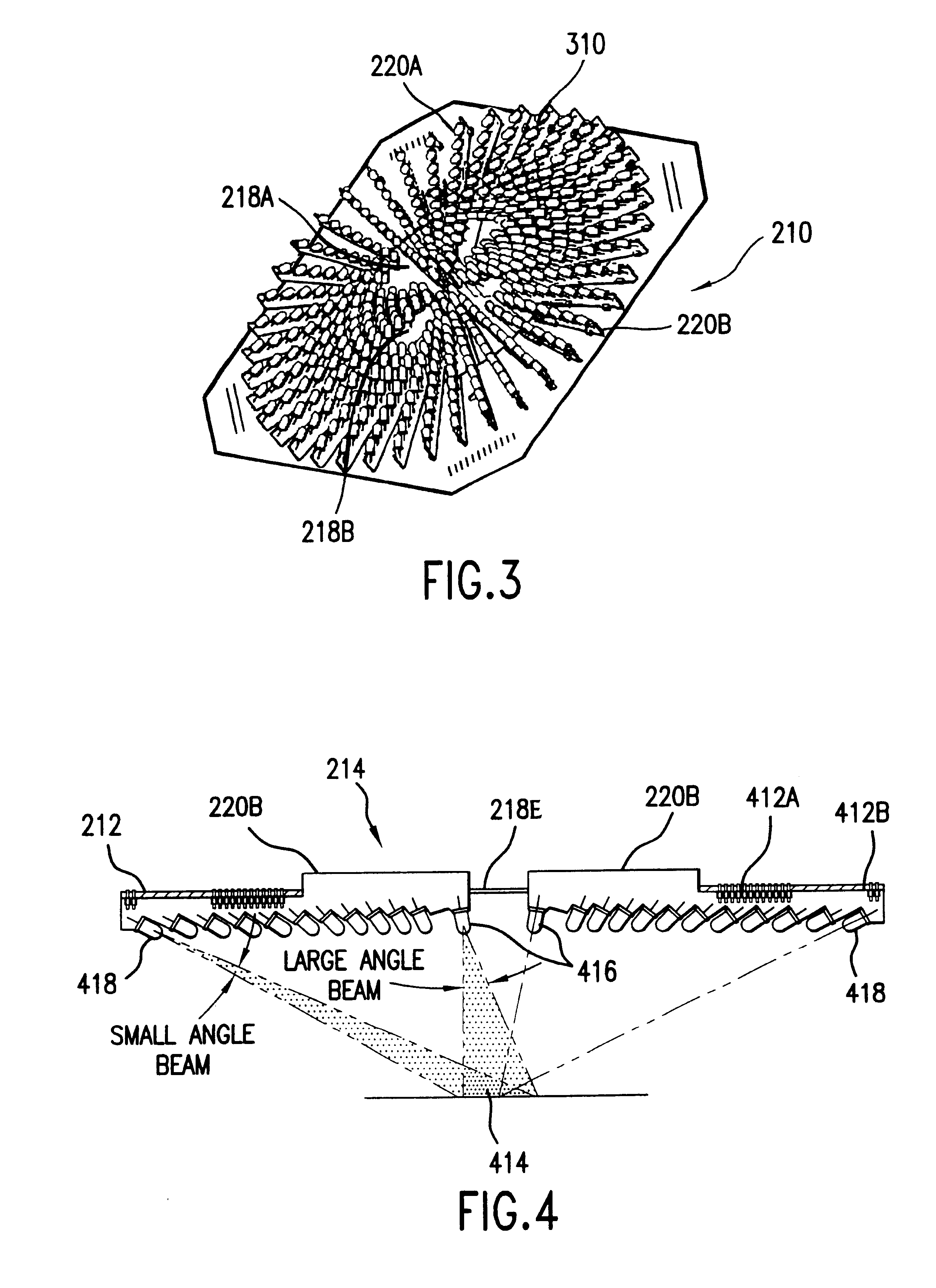
FIG. 2 shows an illumination system 210 according to the invention. In use, illumination system 210 would be used in place of cylinder 30 in FIG. 1. In a preferred embodiment, illumination system 210 is used in an automated optical inspection system for printed circuit boards. Illumination system 210 would provide lighting on the board at various stages of its manufacture. It can be used to provide lighting for inspection of printed circuit boards with tall components such that the clearance between the illumination system 210 and the surface of the board being inspected must be 1.7 mm or more.

Such a system would be used in the manufacture of printed circuit boards. Circuit boards are often inspected at several steps during their manufacturing process. The inspection is sometimes used to alter the work flow for the individual boards. For example, if an inspection reveals a missing component on the board, the board might be re-routed for rework. The precise manner in which the system...


PUM


Abstract

An optical inspection system with an improved illumination system. The improved illumination system used to illustrate the invention has a base formed from a printed circuit board. Substrates for mounting lighting elements, which are exemplified by light emitting diodes, are formed also on printed circuit boards. These circuit boards have serrated edges and the diodes are mounted to the serrations. This configuration allows the light emitting elements to be focused on the focal point. Also in the exemplary illumination system, the light emitting elements have different beam widths so that variations in the illumination intensity as a function of elevation angle are reduced.

Description

This invention relates generally to automated optical inspection systems and more specifically to the lighting arrangement for such inspection systems.Automated optical inspection is used during the manufacture of printed circuit boards and in other fields. A computer controlled system passes a camera over the printed circuit board or other object being inspected and takes images of various regions on the board. The images are then scanned by the computer to verify that features expected to be present in a properly manufactured board are in that region and have an expected shape. Alternatively, the system might verify that there are no features in that region that should not be present. If the features are verified, the board passes inspection. If they are not verified, the board is either labeled as defective or passed on for human inspection or additional testing.When the object being inspected in a printed circuit board, the features of interest will be things such as edges of el...

Claims


Application Information

Patent Timeline
IPC IPC(8): G01N21/956G01N21/88H05K13/08H05K13/00G01B11/24G01N21/84
CPCG01N21/8806G01N21/95684H05K13/08G01N2021/8816G01N2021/95669G01N2201/062G01N2021/95638G01N21/956
Inventor BURNETT, JOHN B.
Owner LANDREX TECH CO LTD
Why Eureka
Try Eureka