Base, payload and connecting structure and methods of making the same

a technology of base, payload and connecting structure, applied in the field of optical devices, can solve the problems of often failing to align optical components with high intrinsic precision, and achieve the effects of reducing stiffness, high intrinsic precision, and high accuracy

Inactive Publication Date: 2005-02-01
DIGITALPTICS MEMS
View PDF28 Cites 70 Cited by
  • Summary
  • Abstract
  • Description
  • Claims
  • Application Information

AI Technical Summary

Benefits of technology

DOFs with different levels of stiffness may be accomplished using a flexure system to relieve stiffness in unwanted DOFs. Depending on the cross-sectional properties of elements in the flexure system, connecting elements between two bodies may attain the desired stiffness connectivities.
The alignment assemblies and methods of making the assemblies according to the invention may provide a number of advantages. For example, the micromachined passive alignment assemblies may be made with high intrinsic precision. Micro machining processes may form three-dimensional structures from a substrate wafer with high accuracy. In several embodiments, one micromachined passive alignment assembly may be oriented and spaced with respect to another a

Problems solved by technology

Such assemblies often fail to align optica

Method used


Image

  • Base, payload and connecting structure and methods of making the same
  • Base, payload and connecting structure and methods of making the same
  • Base, payload and connecting structure and methods of making the same

Examples


Embodiment Construction

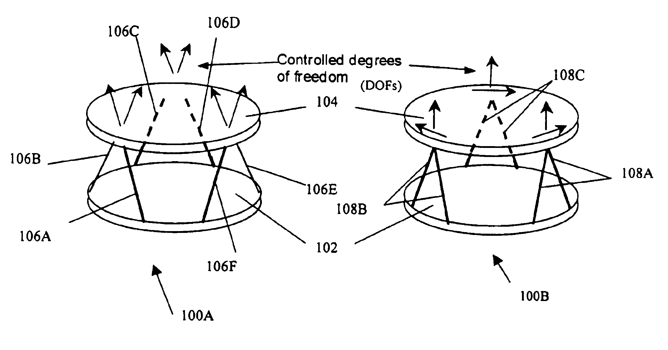
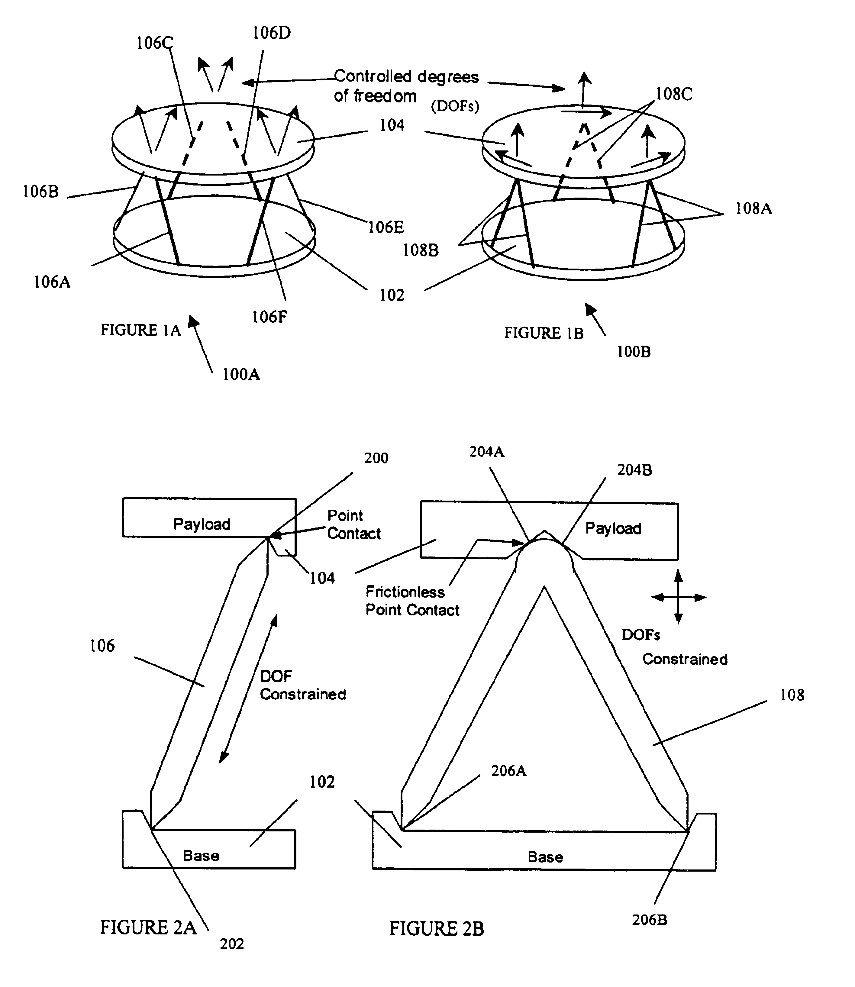
FIG. 1A is a three-dimensional schematic view of one kinematic support configuration 100A. The kinematic support configuration 100A in FIG. 1A comprises a base assembly 102, a payload assembly 104 and six monopod connecting elements 106A-106F (individually or collectively referred to herein as “monopod connecting element 106”). In one configuration, the base assembly 102 is a base support structure, and the payload assembly 104 holds or aligns an optical element, such as an optical fiber, lens or mirror. The base assembly 102 is connected to the payload assembly 104 via the six monopod connecting elements 106A-106F.

Each monopod connecting element 106 in FIG. 1A constrains one degree of freedom (hereinafter referred to as ‘DOF’) between the base assembly 102 and the payload assembly 104, as shown by an arrow above the kinematic support configuration 100A in FIG. 1A. A constrained DOF may be referred to as a ‘stiff’ DOF or a restrained DOF. The relevant reference parameter for transla...


PUM


Abstract

Micromachined passive alignment assemblies and methods of using and making the same are provided. The alignment assemblies are used to align at least one optical element. The alignment assemblies may be configured with kinematic, pseudo-kinematic, redundant or degenerate support structures. One alignment assembly comprises a base and a payload, which supports at least one optical element. The payload may be coupled to the base via connecting structures. The base, the payload and/or the connecting structures may have internal flexure assemblies for preloading a connection, thermal compensation and/or strain isolation.

Description

BACKGROUND OF THE INVENTION1. Field of the InventionThe present invention relates generally to optical devices, and more particularly to optical element alignment assemblies and methods of making the same.2. Description of the Related ArtAn optical component, such as a mirror, lens or fiber, in an optical instrument or device, such as an optical switch, should be accurately located / positioned with respect to another optical component in order for the optical instrument or device to function properly. Thus, optical devices may require their components to be placed with exacting tolerances to fulfill design objectives.Conventional passive alignment assemblies for MicroElectroMechanical System (MEMS) devices are typically planar in nature and only align local elements, e.g., a fiber and ball lens collimator, where the two components are within a few millimeters of each other. Alignments over larger distances (e.g., greater than five millimeters), and three-dimensional optical systems t...

Claims


Application Information

Patent Timeline
IPC IPC(8): G02B7/00
CPCG02B7/008G02B7/003
Inventor CALVET, ROBERT J.GUTIERREZ, ROMAN C.TANG, TONY KAI
Owner DIGITALPTICS MEMS
Why Eureka
Try Eureka