Image trap filter

a filter and image technology, applied in the field of frequency conversion mixers, can solve the problems of image rejection and monolithic integration, large and expensive ceramic or surface, excessive size, weight, cost,

Inactive Publication Date: 2005-02-01
XUESHAN TECH INC
View PDF25 Cites 22 Cited by
  • Summary
  • Abstract
  • Description
  • Claims
  • Application Information

AI Technical Summary

Benefits of technology

To overcome the shortcomings of the prior ways of achieving image signal rejection with an image trap filter considered above, a new image trap filter is provided by the present invention. One object of the present invention is to provide a new and improved image trap f

Problems solved by technology

Among the important problems faced by the designers of radio receivers are image rejection and monolithic integration.
Otherwise, the subsequent detector circuit will be unable to distinguish between the desired signal and the image signal and, therefore, the output will be the result of the superposition of both.
In conventional heterodyne receiver architectures, a large and expensive ceramic or Surface Acoustic Wave (SAW) filter is positioned between the low noise amplifier and the mixer to suppress the image signal.
The arrangement defies integration, however, and results in excessive size, weight, and cost.
Image reject mixers in which phasing methods are used are at best, however, only capable of achieving 30 dB of image rejection over the typical temperatures and processes used.
The limitation, in terms of reliable image rejection from the phasing methods, comes from the required amplitude and phase imbalance in the local oscillator quadrature generation and intermediate frequency quadrature combining.
This approach results in an excess inductance in the desired band that must be tuned out.
This approach suffers, however, fro

Method used


Image

  • Image trap filter
  • Image trap filter
  • Image trap filter

Examples


Embodiment Construction

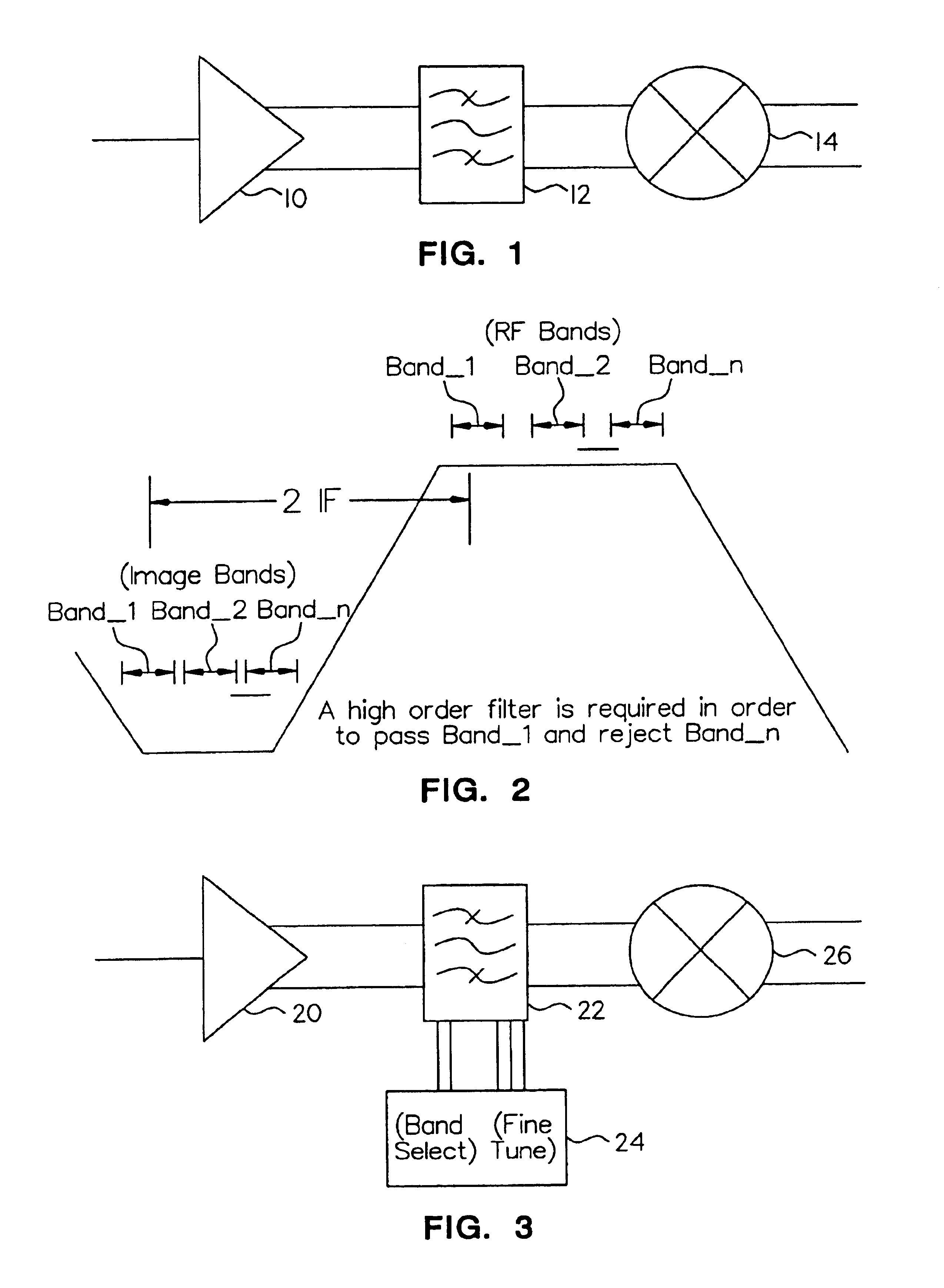
FIG. 3 is a schematic drawing of a portion of a radio frequency receiver that incorporates an image trap filter constructed in accordance with the present invention. In FIG. 3, a radio frequency signal is received by a low noise amplifier 20 and, after amplification, is supplied to an image trap filter 22 constructed in accordance with the present invention. Image trap filter is tunable by means represented by block 24 to select a band when incorporated in a multi-band radio frequency receiver and to filter the image signal from the amplified radio frequency signal. The radio frequency signal then is supplied to a mixer 26 that develops the intermediate frequency signal from the radio frequency signal.

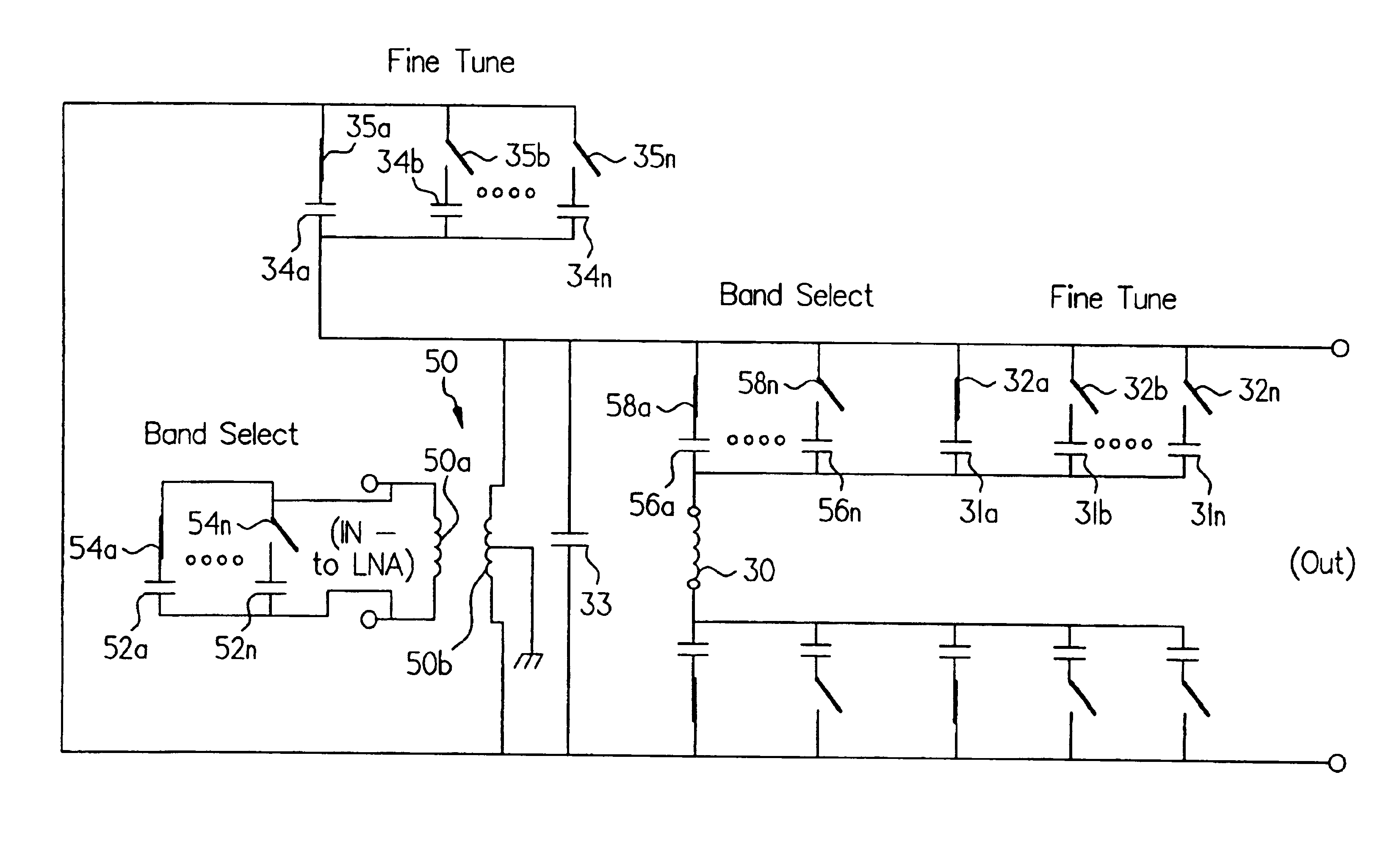
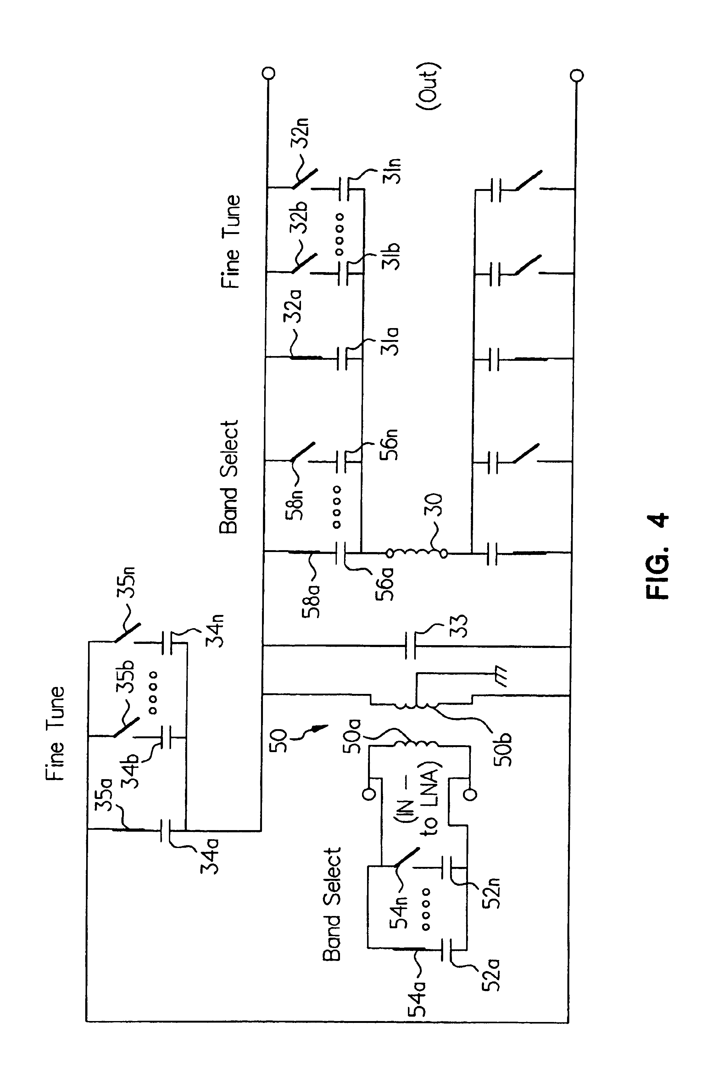
Referring to FIG. 4, an image trap filter for filtering an image signal from a radio frequency signal, constructed in accordance with a first embodiment of the present invention and arranged for low-side injection of the local oscillator frequency, includes a first branch having an ind...


PUM


Abstract

An image trap filter disposed between the low noise amplifier and the mixer of a radio frequency receiver that overcomes the adverse effect of process variations on image signal rejection for both a single-band radio frequency receiver and a multi-band radio frequency receiver by setting the image trap filter response at the center of the band of interest at production test. The image signal problem is presented at the input of the radio frequency receiver and the image trap filter is adjusted for the desired frequency response.

Description

TECHNICAL FIELDThe present invention relates, in general, to the rejection of the image signal of a radio frequency signal converted to an intermediate frequency and, in particular, to a frequency conversion mixer especially suited to be implemented on an integrated circuit.BACKGROUND OF THE INVENTIONUnlike wireline communications, the wireless environment accommodates essentially an unlimited number of users sharing different parts of the frequency spectrum and very strong signals coexist next to very weak signals. A radio receiver must be able to select the signal of interest, while rejecting all others.Among the important problems faced by the designers of radio receivers are image rejection and monolithic integration. A radio receiver must be able to select the desired signal from its image. Otherwise, the subsequent detector circuit will be unable to distinguish between the desired signal and the image signal and, therefore, the output will be the result of the superposition of...

Claims


Application Information

Patent Timeline
IPC IPC(8): H03H7/01
CPCH03H7/0115H03H7/1775H03H2210/015H03H2210/012H03H2007/013
Inventor IMBORNONE, JAMES F.MOURANT, JEAN-MARC
Owner XUESHAN TECH INC
Why Eureka
Try Eureka