
Method and system for developing a software program using compound templates

a software program and template technology, applied in the field of system development of software programs, can solve the problems of difficult to create such a specialized template, laborious renaming and cross-referencing, and inability to properly rename variables, and achieve the effect of easy generation

Inactive Publication Date: 2005-02-01
ROCKWELL SOFTWARE
View PDF5 Cites 38 Cited by
  • Summary
  • Abstract
  • Description
  • Claims
  • Application Information

AI Technical Summary

Benefits of technology

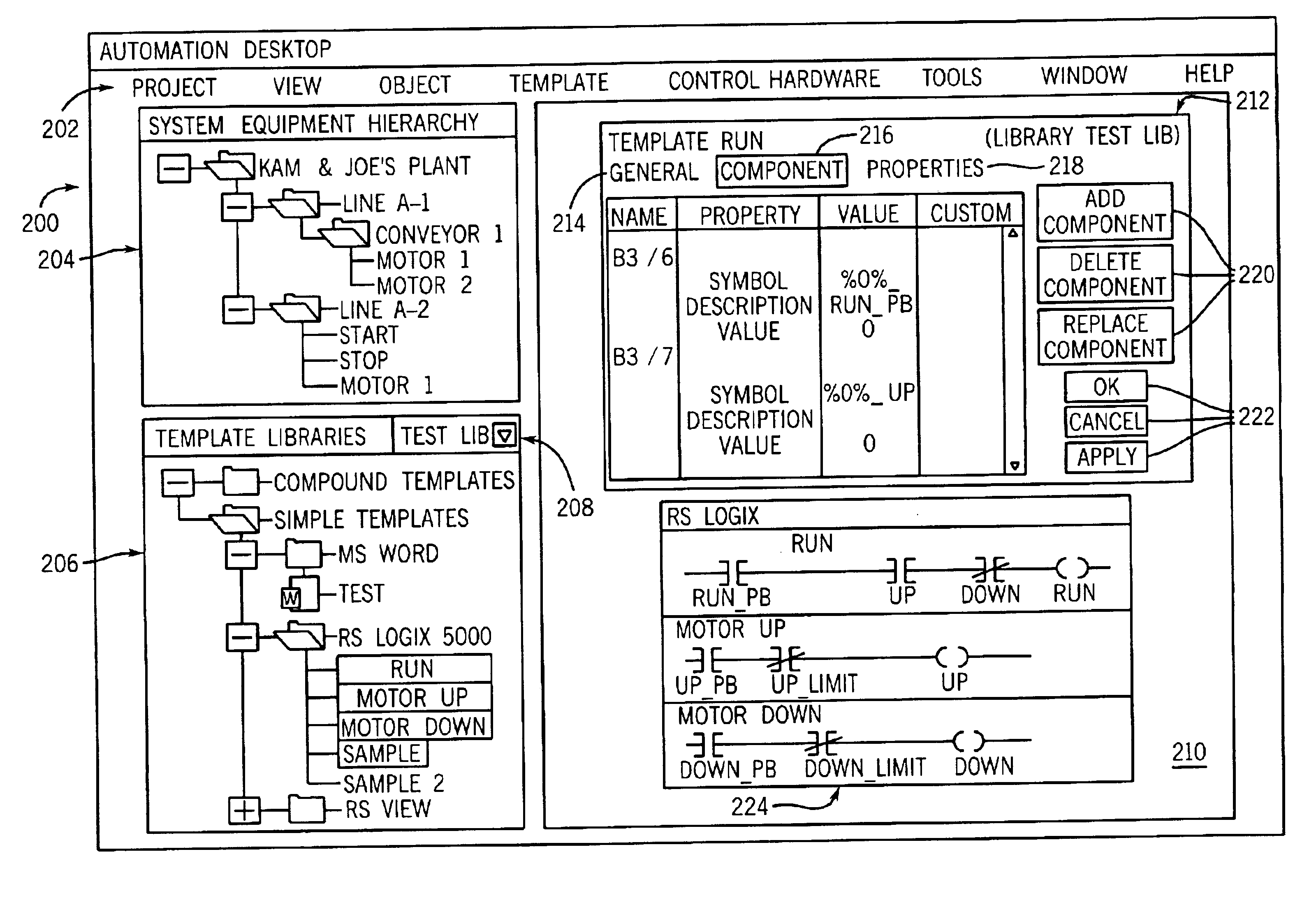
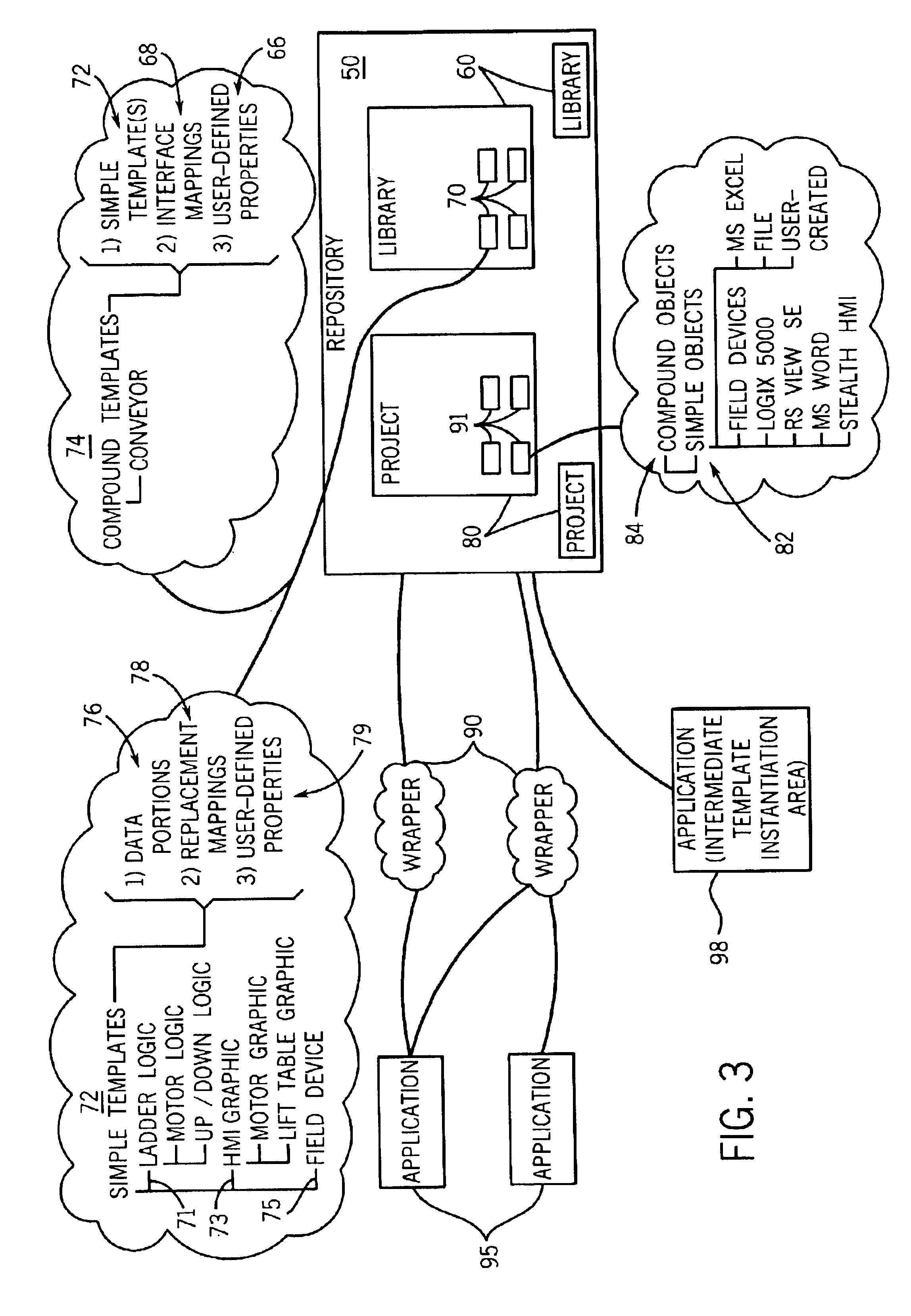
The present inventors have recognized that the existing method and system for developing control programs could be improved by including with that system an additional program that was able to extract relevant control variable names from templates. Once those variable names were extracted, corresponding variable names from related templates could be displayed to the program designer in a tabular format, with the program designer being presented with an opportunity to create substitute “interface” variable names or tags that would globally replace related control variable names throughout all of the related templates. By substituting such interface tags throughout the templates, truly “compound” templates could be generated with ease using the modular, lower-level “simple” templates. Upon the interface tags being specified, the normal instantiation process could continue, with variable names being automatically modified to correspond to the particular system components for which the control program was being designed.

Problems solved by technology

This renaming and cross-referencing is a laborious task.
On such occasions, the above-described system is only able to properly rename the variables of the templates at the lowest level.
Yet the creation of such a specialized template would in itself be complicated.
Further, the creation of such a specialized template would eliminate the benefits associated with creating control programs by way of lower-level, simpler, more modular templates such as those representing the motors.

Method used


Image

  • Method and system for developing a software program using compound templates
  • Method and system for developing a software program using compound templates
  • Method and system for developing a software program using compound templates

Examples


Embodiment Construction

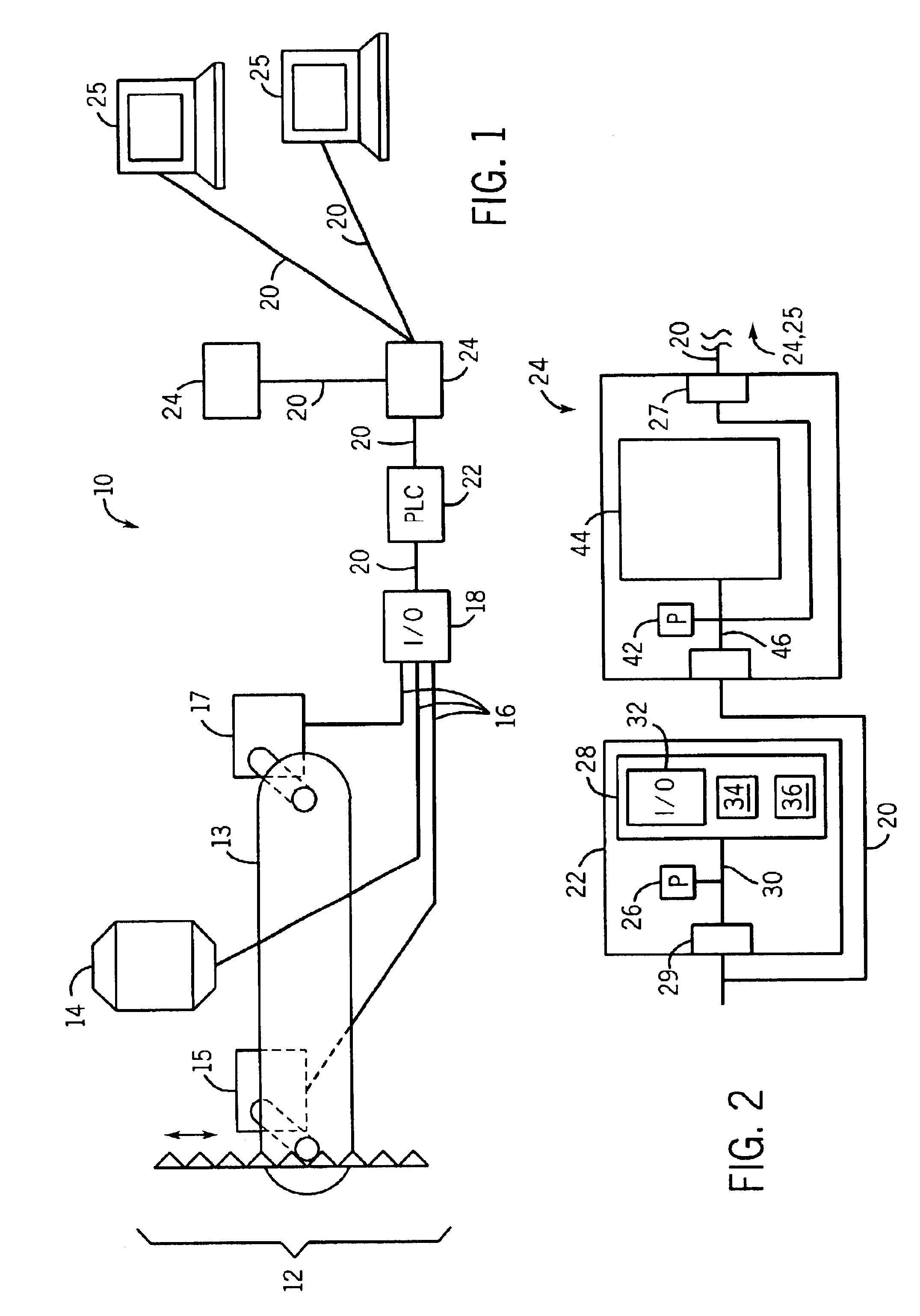
Referring now to FIG. 1, an industrial control system 10 is used to control a process 12 which, for example, may include components such as a tank 14, as well as a conveyor 13 operated by first and second motors 15 and 17, which respectively control movement of a conveyor table up and down and control movement of the conveyor belt. The process 12 may be controlled according to control variables communicated over lines 16. The control variables may be output signals controlling actuators (e.g., the motors 15,17) or may be inputs from sensors (e.g., on the tank 14) such as temperature sensors, motion sensors or level sensors.

The lines 16 are received by I / O circuits 18 providing for basic signal processing known in the art and for the conversion between analog signals and digital values for computer processing. The digital values may be communicated over a communication link 20 between the I / O circuits 18 and a programmable logic controller (or PLC) 22. The programmable logic controll...


PUM


Abstract

A method and system are disclosed for creating programs executable on an industrial controller to control an industrial process. The method includes providing a plurality of templates from at least one library, where each template has at least one respective control variable. The method also includes receiving selections of at least some of the plurality of templates, and identifying at least some of the control variables as replacement fields. The method further includes creating at least one interface mapping to link to the replacement fields, where the first and second templates linked by the interface mapping form at least a portion of a compound template. The method additionally includes instantiating an object using the compound template, where the object forms at least a portion of the control program.

Description

FIELD OF THE INVENTIONThe present invention relates to systems for developing software programs for use in a variety of a environments including, for example, programs for controlling industrial processes or manufacturing equipment.BACKGROUND OF THE INVENTIONComputer programs are implemented in countless ways in modern life to provide control, monitoring and other capabilities to a variety of systems. Although some standardized programs are used ubiquitously, many (if not most) modern systems require at least some programming that is uniquely tailored for the particular purposes of the systems. For example, industrial controllers, which are commonly used for controlling industrial processes or manufacturing equipment, typically require control programs that are uniquely designed for the particular industrial process. Accordingly, it is important to be able to efficiently and easily develop such programs. In this regard, it is known to reuse elemental portions of other control progra...

Claims


Application Information

Patent Timeline
Patent Type & Authority Patents(United States)
IPC IPC(8): G05B19/04G05B19/042G06F9/44
CPCG05B19/0426G05B2219/23008G05B2219/23067G05B2219/25428G05B2219/23261G05B2219/23292G05B2219/23258
Inventor YUEN, KAM-PORBRONIKOWSKI, JOSEPH T.ROBAK, PAUL T.WEBER, JASON A.
Owner ROCKWELL SOFTWARE
Learn More