Power-assisted bicycle

a technology of power-assisted bicycles and bicycles, which is applied in the direction of clutches, freewheel clutches, vehicle components, etc., can solve the problems of large space, increased weight of torque detection systems, and the need to significantly modify the body frame of conventional bicycles, and achieves simple and lightweight structure and economic

Inactive Publication Date: 2005-02-08
SUNSTAR GIKEN KK +1
View PDF15 Cites 37 Cited by
  • Summary
  • Abstract
  • Description
  • Claims
  • Application Information

AI Technical Summary

Benefits of technology

With the above circumstances taken into account, the present invention has been completed and has the object to provide a power-assisted bicycle that can use a conventional body frame modified only slightly, as well as achieve a simple and lightweight structure of a torque detection mechanism system that is also economical in terms of space.
In accordance with the present invention, the assisting power is controlled on the basis of the physical amount that varies with the deformation of the one-way clutch system requisite for the bicycle in accordance with the pedaling force. Therefore, the power-assisted bicycle according to the present invention can achieve the desired object without the addition of a separate part, such as a large-sized coil spring or a disk for use in detecting torque, which is not used in a conventional bicycle. Further, for the power-assisted bicycle according to the present invention, the elastic member may preferably be disposed such that it resists the deformation of the one-way clutch system. Still further, the elastic member is not required to be large because it does not undergo the competitive stress directly while it undergoes a force in the direction of deformation through the one-way clutch system. Moreover, the amount of deformation of the one-way clutch system can be rendered smaller so that an elastic member having a generally flat structure lower in height than in breadth can be disposed in such a manner that the direction of height of the elastic member is aligned with in the direction of deformation of the one-way clutch system. This can save a considerable amount of space. Such a generally flat elastic member may include, for example, a disc spring.
In this embodiment, the effects of the present invention can further be improved because the one-way clutch system as an essential structuring part is used as the torque detection mechanism system, and the disc spring integrating a backing load unit with a load detection sensor is used for the elastic member and a portion for detecting the pedaling torque. Therefore, the power-assisted bicycle according to the present invention can be implemented with few modifications to the frame structure of a conventional bicycle and can be lightweight, simple in structure as well as quiet while in use.

Problems solved by technology

These technologies, however, present a problem in that, due to the installment of the torsion bar on the crank shaft or the like, a large space is required for installing the torque detection system and the weight of the torque detection system is increased, making it necessary to considerably modify the body frame of a conventional bicycle.
Another problem is that the cam or any other suitable element has to be disposed in order to convert the torsion deformation of the torsion bar into a direct linear movement, or a system for directly detecting an angle of rotation by the torsion from each of the both ends of the torsion bar is required to be added.
These matters may also create a problem in that the mechanism is rendered more complicated.
However, it does not adequately solve the problem of saving space for the torque detection mechanism system due to the elongation of the crank shaft as a whole in the axial direction, because the coil spring is supported by the frame coaxially with the crank shaft, the coil spring being arranged so as to be elongated or contracted in the axial direction due to expansion or contraction of its diameter in accordance with the magnitude of the pedaling torque.
Moreover, the addition of the heavy and large-sized coil spring presents a problem with the lightweight structure of the torque detection mechanism system because the coil spring is high in rigidity and in modulus of elasticity so as to withstand the pedaling force.
Furthermore, this bicycle has a problem with a feeling of resistance when pedaling since it remains when pedaling.
This arrangement, however, cannot save a sufficient amount of space or be of a structure lightweight enough for the torque detection mechanism system, similar to the prior technology described immediately above.

Method used


Image

  • Power-assisted bicycle
  • Power-assisted bicycle
  • Power-assisted bicycle

Examples


first embodiment

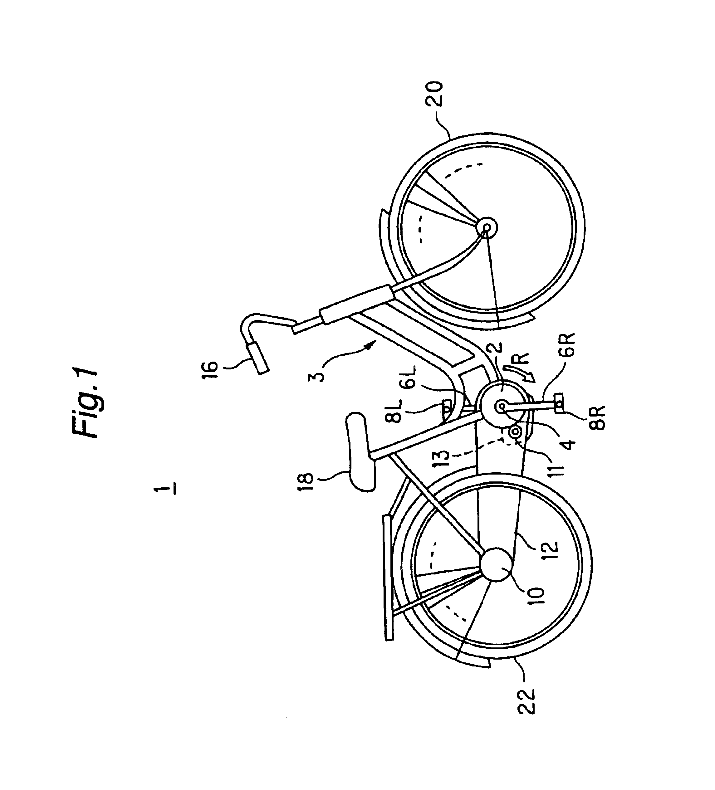
FIG. 1 is a brief representation of a power-assisted bicycle 1 according to the first embodiment of the present invention. As shown in FIG. 1, a major skeleton structure of the power-assisted bicycle 1 comprises a body frame 3 made of a metallic tube, and various elements including a front wheel 20, a handlebar 16 for steering the front wheel, a rear wheel 22, a saddle 18 and so on which are mounted on the body frame 3 in a conventional manner as with an ordinary bicycle.

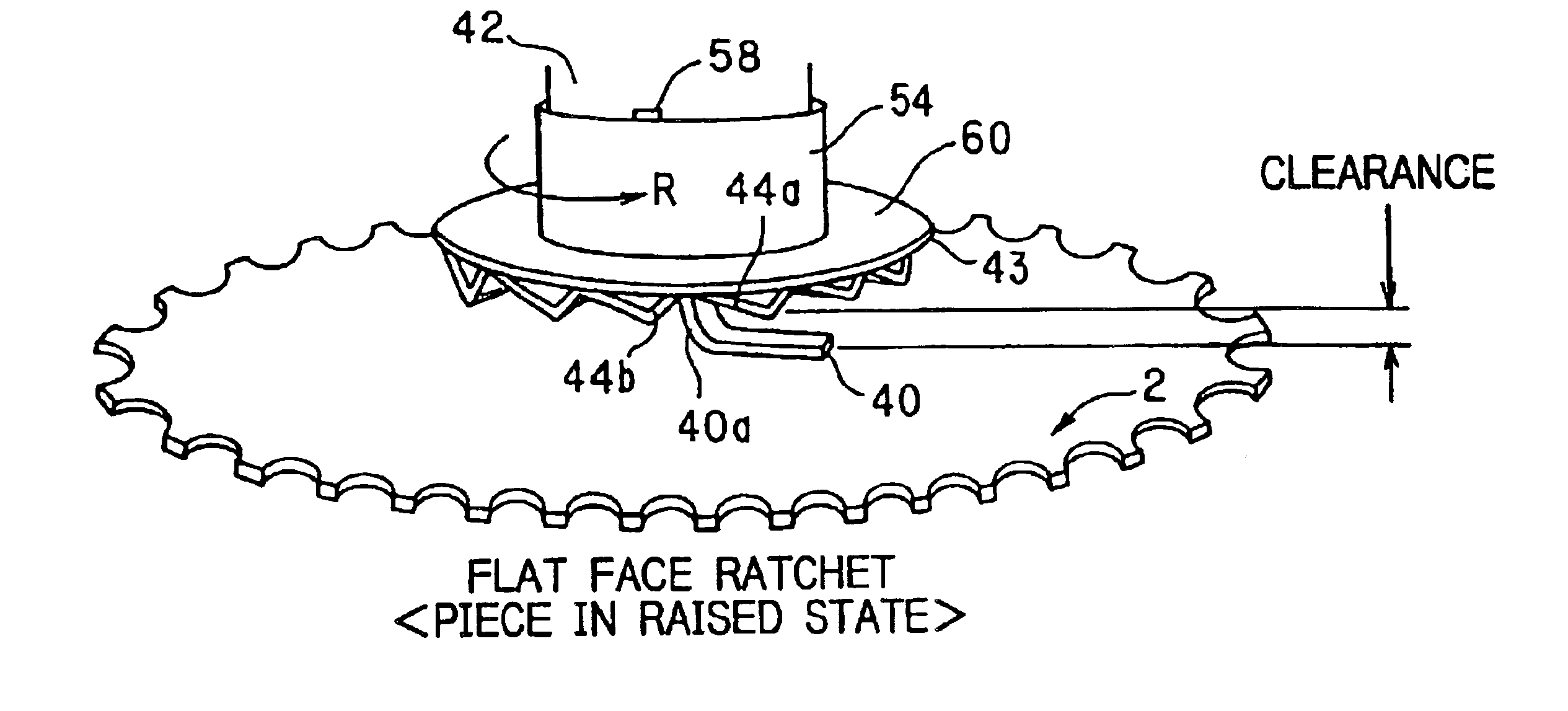
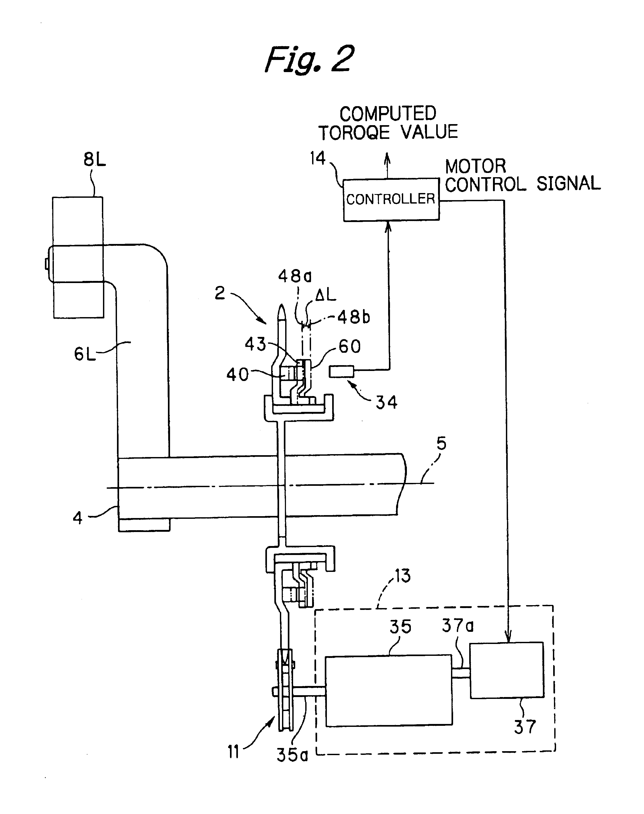
At a central lower portion of the body frame 3, a drive shaft 4 is held on the body frame 3 so as to be rotatable, and pedals 8L and 8R are mounted at the left-hand and right-hand end portions of the drive shaft 4 through crank shafts 6L and 6R, respectively. A sprocket 2 (acting as the driven side) is coaxially mounted on the drive shaft 4 (acting as the driving side) through a ratchet gear, as will be described in more detail, and the ratchet gear is arranged to transmit only the rotational torque in a one-way dir...

second embodiment

FIGS. 8(A)and 8(B) each illustrate a torque detection mechanism system in accordance with a second embodiment of the present invention. In this embodiment, the elements other than the torque detection mechanism system are the same as those of the first embodiment, so that identical and like structuring elements are provided with identical reference numerals and symbols and a duplicate detailed description thereof will be omitted for brevity of explanation.

As shown in FIGS. 8(A) and 8(B), the torque detection mechanism system of the second embodiment is provided with a sprocket 70 having a cylindrical accommodation part 82 at the central portion thereof. The cylindrical accommodation part 82 is shaped in a cylindrical form that protrudes toward a first plate face side of the sprocket 70 and is depressed on the other (second) plate face side thereof. The sprocket 70 may be disposed so that the depression of the cylindrical accommodation part 82 is directed to the pedal side, and the d...

third embodiment

The third embodiment can offer pronounced advantages and merits as will be summarized below.

(1) The ratchet gear and the torque detection mechanism system can be implemented by one mechanism system, so that the number of parts can be reduced. As a consequence, the bicycle can be rendered more compact in size and lighter in weight as well as being manufactured at lower cost than conventional ones.

(2) The disc spring with a unit for receiving a load imposed upon pedals and a load (torque) detection sensor integrated therein is used at the portion at which the pedaling torque is to be detected. Therefore, the two functions can be implemented by one unit, achieving a further compactness and lightness of structure and further reducing costs of manufacturing, in addition to the effects as described above.

(3) The present invention can achieve a compact, lightweight and simple structure of the torque detection mechanism system at a very high level as has been described in (1) and (2) above....


PUM


Abstract

A power-assisted bicycle includes a torque detection mechanism system that is simple in structure, saves space, and is lightweight. A one-way clutch (72) for transmitting only rotation of the drive shaft (4) to the sprocket (70) in the direction in which the bicycle proceeds is disposed inside a hollow cylindrical portion (82) of the sprocket (70). On the sprocket face opposite thereto, a bearing (74) is engaged with an outer periphery of the cylindrical portion (82), and an elastic disc spring (76) holds the sprocket (70) with the aid of the bearing. The disc spring (76) is fixed to the bicycle body and a strain gauge (80) for detecting a stress deformation of the disc spring (76) is mounted on the surface thereof. As the drive shaft (4) is rotated by the aid of the pedaling torque, the one-way clutch (72) exerts an axially pressing force onto the sprocket (70) to deform the disc spring (76), and the strain gauge (80) detects the stress deformation of the disc spring (76) (that is, a physical parameter associated with the pedaling torque).

Description

TECHNICAL FIELD OF THE INVENTIONThe present invention relates to a power-assisted bicycle arranged so as to add an assisting power to a pedaling force. More particularly, the present invention relates to a power-assisted bicycle with a torque detection system installed in a one-way clutch unit that transmits only a one-way rotation of a drive shaft to a sprocket.BACKGROUND OF THE INVENTIONHeretofore, there has been proposed and applied a power-assisted bicycle arranged to assist a pedaling force by detecting a pedaling torque acting on a rotational mechanism in accordance with the pedaling force and applying an electric torque on the basis of a variation in the pedaling torque detected. Such a power-assisted bicycle is provided with a torque detection system for detecting the pedaling torque, which includes a torsion bar mounted in a crank shaft or on a rear wheel shaft, which causes a torsion deformation in accordance with the pedaling force. Further, this torque detection system m...

Claims


Application Information

Patent Timeline
Patent Type & Authority Patents(United States)
IPC IPC(8): B62M23/02B62M6/45B62M6/50B62M6/55
CPCB62M6/40B62M6/55B62M6/50B62M6/45
Inventor YOSHIIE, AKIHITOKOKATSU, KYOSUKE
Owner SUNSTAR GIKEN KK
Why Eureka
Try Eureka