Seat belt tension sensor assembly

a technology of tension sensor and seat belt, which is applied in the direction of instruments, pedestrian/occupant safety arrangements, force/torque/work measurement apparatus, etc., can solve the problems of seat weight sensor false and inaccurate readings, seat occupant weight sensor arrangement is not as integrated into the overall seat belt assembly as desired, and achieves the effect of increasing the integration level of the tension sensor assembly, improving detection, and increasing the magnetic field intensity

Inactive Publication Date: 2005-02-08
DELPHI TECH INC
View PDF10 Cites 51 Cited by
  • Summary
  • Abstract
  • Description
  • Claims
  • Application Information

AI Technical Summary

Benefits of technology

s set forth in the Background. One advantage of the present invention is that allows a higher level of integration of the tension sensor assembly into the seat belt system. According to the invention, a seat belt tension sensor assembly comprises a housing, a slider slidably received within the housing, the slider being configured for movement between a first position and a second position within the housing, a first and second magnet associated with the slider for slidable movement therewith, the first and said second magnets being positioned side by side with opposite polarization, a Hall effect device being fixed relative to the housing and protruding between the first and the second magnets when the slider is in the second position, the Hall effe...

Problems solved by technology

There are, however, several problems with detecting seat occupant weight.
For example, when a seat occupant puts on the seat belt, the force of cinching the seat belt across ones' lap can cause a seat weight sensor to have false and inaccurate readings.
Another example is when a child's safety seat is cinched tightly in the car seat, it can appear t...

Method used


Image

  • Seat belt tension sensor assembly
  • Seat belt tension sensor assembly
  • Seat belt tension sensor assembly

Examples


Embodiment Construction

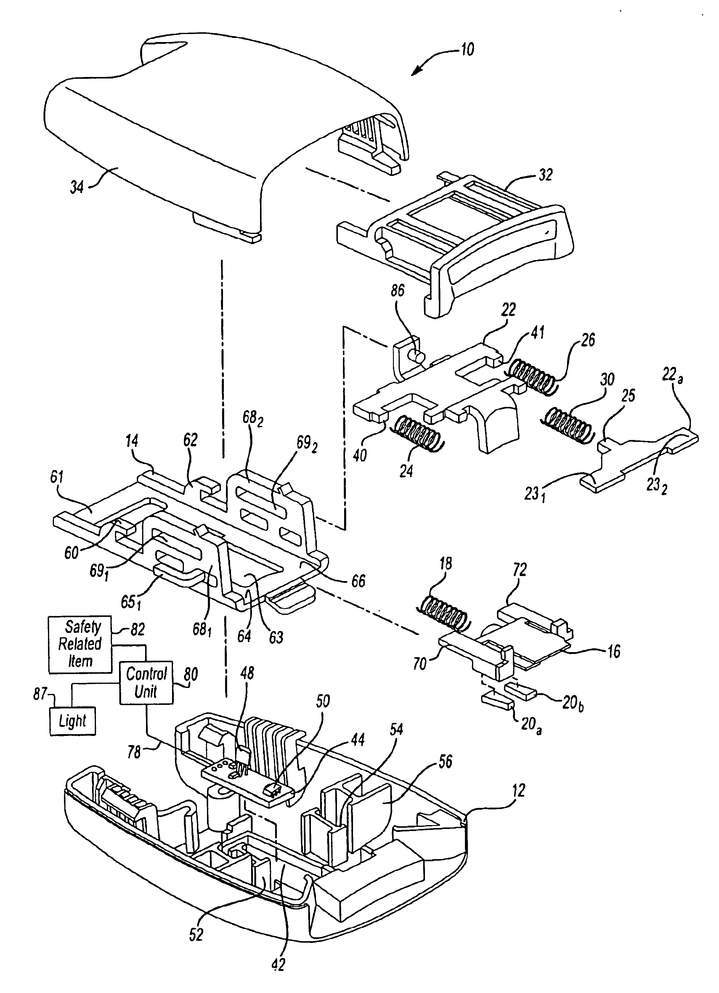
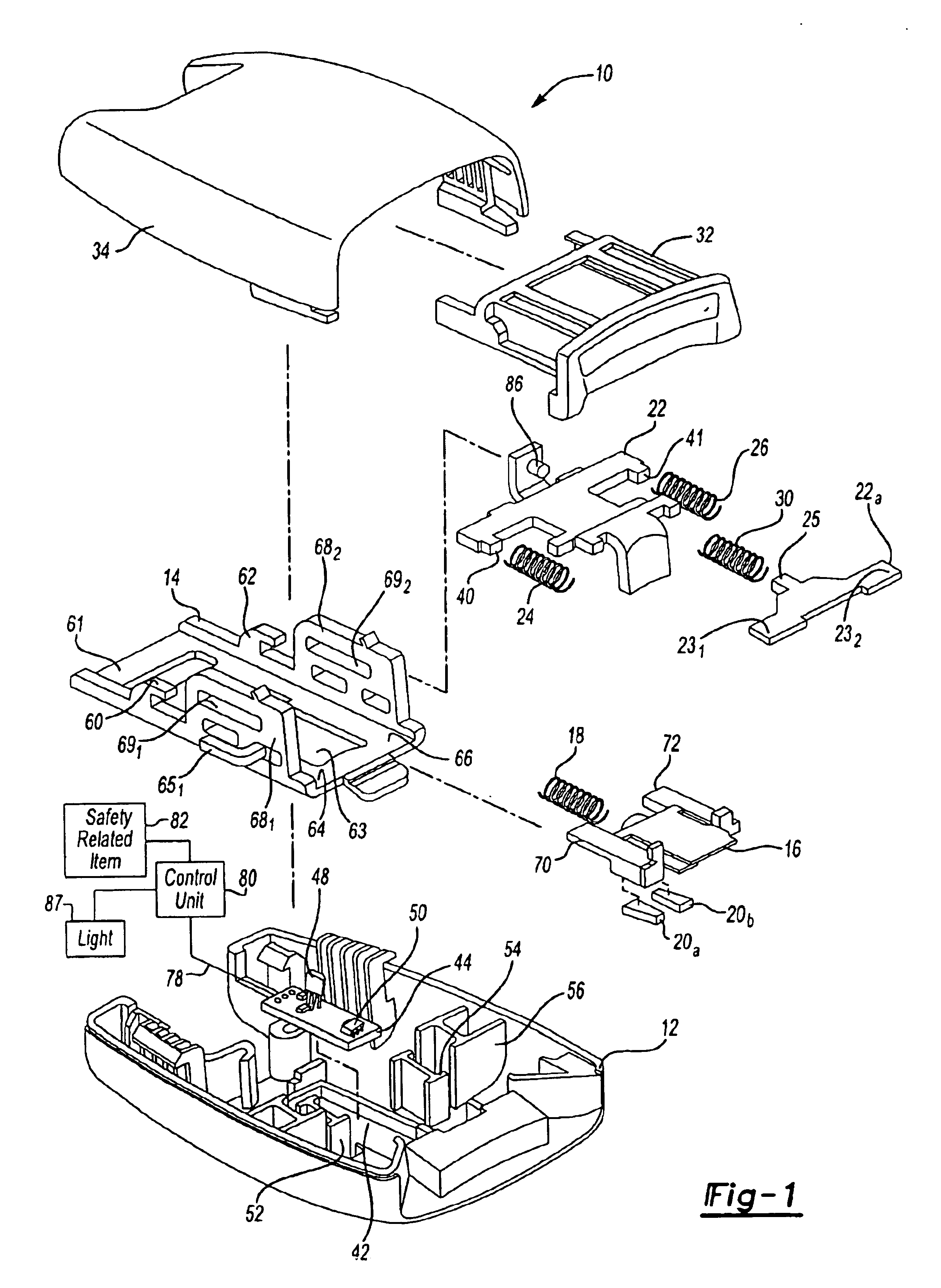
Referring now to the drawings wherein like reference numerals are used to identify identical components, FIG. 1 an assembly view of the seat belt tension sensor assembly generally indicated by 10. The seat belt tension sensor assembly 10 includes a bottom cover 12, a buckle 14, a slider 16, spring 18, a pair of magnets 20a and 20b, hook portions 22 and 22a, biasing members 24 and 26, a spring 30, a release button 32 and an upper cover 34.

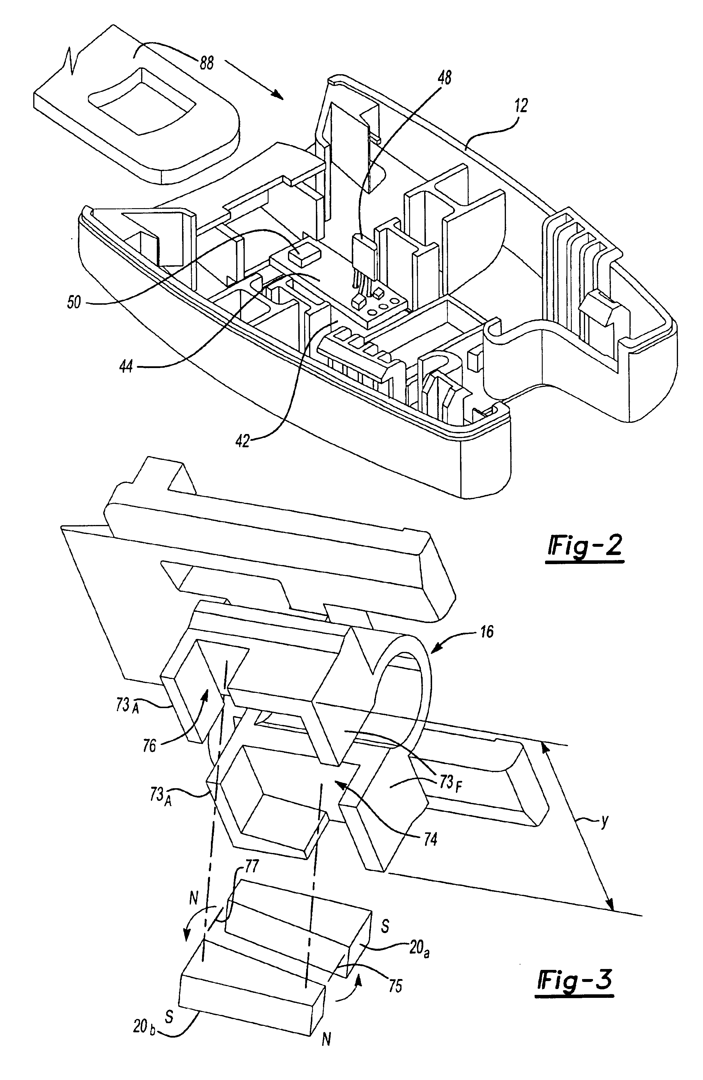
Bottom cover 12 and upper cover 34 form a housing, which may be constructed out of a lightweight, easily-molded material such as plastic. Bottom cover 12 includes cavity 42 configured in size and shape to receive a printed circuit board (PCB) 44. PCB 44 may be mounted in cavity 42, for example, as shown. Printed circuit board 44 includes a Hall effect device 48 or other sensor capable of detecting a magnetic field. Device 48 is arranged so that it protrudes generally in a normal direction outwardly from PCB 44. PCB 44 also includes a second sensor, ...


PUM


Abstract

A seat belt tension sensor assembly includes a housing, a slider slidably received within the housing, wherein the slider is configured for movement between a first position and a second position within the housing, and a first and second magnet associated with the slider for slidable movement therewith. The first and the second magnets are positioned side by side with opposite polarization. A hall effect device is fixed relative to the housing and protrudes between the first and the second magnets when the slider is in the second position. The hall effect device is configured to produce an output signal, the output signal being indicative of a seat belt tension of a seat belt as applied to the sensor assembly. A biasing member provides an urging force to the slider, the urging force urging the slider into the first position.

Description

TECHNICAL FIELDThe present invention relates generally to a safety restraint system, and more particularly to a seat belt tension sensor assembly that can detect the tension and engagement of a seat belt and provide an electrical signal in response thereto.DISCUSSION OF THE BACKGROUND ARTVehicles are provided with seat restraints systems such as a seat belts in order to restrain occupants in the seat. The proper engagement and operation of the seat belt is critical to the safety of a driver and his or her occupants.Seat belts often incorporate sensors that provide data to other vehicle restraint vehicle systems such as airbags. Deployment of an airbag may partially depend on the information supplied by the sensor in the seat belt, such as a sensor may determine the weight of an object in the seat. There are, however, several problems with detecting seat occupant weight. For example, when a seat occupant puts on the seat belt, the force of cinching the seat belt across ones' lap can ...

Claims


Application Information

Patent Timeline
IPC IPC(8): B60R22/00B60R21/01B60R22/48B60R21/015
CPCB60R22/48B60R21/0155B60R2022/4841Y10T24/45665B60R2022/4816
Inventor ALMARAZ, JOSE LPALFENIER, SAMUEL ROLANDGODOY, ARQUIMEDES
Owner DELPHI TECH INC
Why Eureka
Try Eureka