
Shock absorber with adjustable valving

a shock absorber and adjustable technology, applied in the field of shock absorbers, can solve the problems of insufficient rate adjustment of prior art shock absorbers, inability to adjust in a wide range, and inability to adjust in a large range, etc., to achieve the effect of improving characteristics, simple, and cost-effectiv

Inactive Publication Date: 2005-02-08
BOMBARDIER RECREATIONAL PROD INC
View PDF7 Cites 28 Cited by
  • Summary
  • Abstract
  • Description
  • Claims
  • Application Information

AI Technical Summary

Benefits of technology

It is, therefore, an object of the present invention to provide a simple, cost-effective, reliable, shock absorber with improved characteristics.
It is another object of the present invention to provide a shock absorber that maximizes the ease with which an adjustment may be made to the rate at which the shock rod moves in relation to the shock body.
It is still another object of the present invention to provide a shock absorber that maximizes the extent to which an adjustment may be made to the rate at which the shock rod moves in relation to the shock body.
It is yet another object of the present invention to provide a shock absorber that minimizes the possibility that shock fluid may be undesirably discharged from the shock absorber through a vent hole or other aperture opening to the environment.

Problems solved by technology

Many prior art shock absorbers fail to provide sufficient adjustment to the rate at which fluid is permitted to pass through the compression and rebound valves.
Such inadequacies may result from the incorporation of valves with too small an adjustment range.
Other prior art shock absorbers provide no adjustment.
Still others provide adequate adjustment by providing an adjustment knob or selector, but the adjustment knob or selector is positioned such that it is largely inaccessible (or not conveniently accessible) to the vehicle operator.
In these shock absorber designs, the adjustment feature is of little use because the user will likely disregard a feature that is not convenient to use.
In these shock absorber designs, if the pressure of the fluid that enters the reservoir is high and cannot be modulated, the fluid may be undesirably discharged from the shock absorber through the vent hole.
This undesirable discharge is known as leakage and results in diminished shock absorber performance.
It may also have the undesirable effect of covering vehicle parts with shock absorber fluid.
The prior art does not address these aforementioned needs.

Method used


Image

  • Shock absorber with adjustable valving
  • Shock absorber with adjustable valving
  • Shock absorber with adjustable valving

Examples


Embodiment Construction

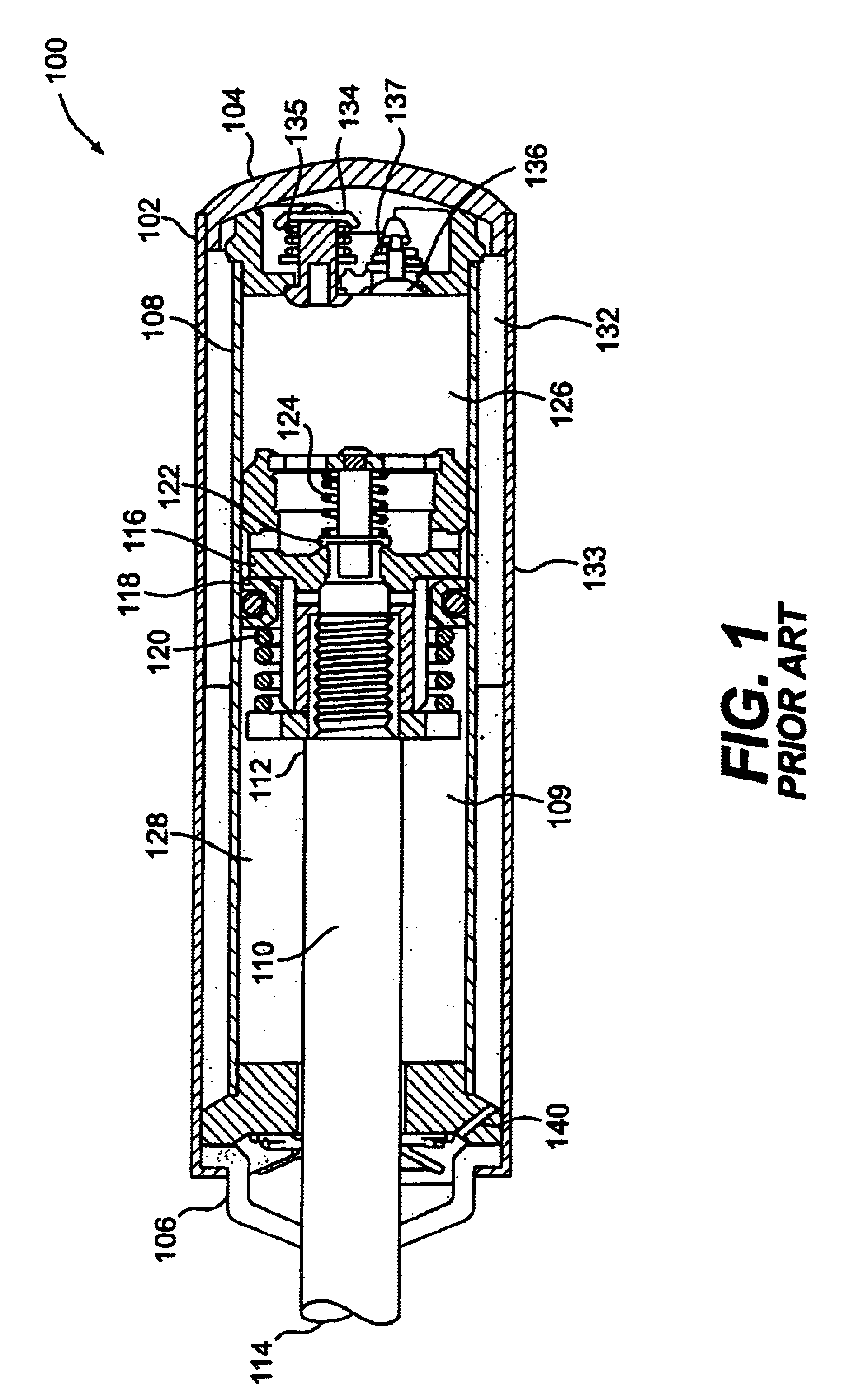
FIG. 1 is a cross-sectional side view of a prior art shock absorber 100. The shock absorber 100 includes a shock body 102 having a first end 104 and a second end 106. The shock body 102 includes a first peripheral wall 108, which is typically cylindrical. The first end 104, second end 106, and peripheral wall 108 define a shock body fluid chamber 109, within which a shock absorber fluid is disposed. The shock absorber includes a shock rod 110 having a longitudinal axis, a first end 112 disposed within the shock body fluid chamber 109, and a second end 114 extending from the shock body second end 106 to a location where the second end is disposed outside the shock body 102. Although not shown, it is understood that the shock rod second end 114 would typically include a rod eye or other structure suitable for connecting the shock rod 110 to a vehicle.

A piston 116 is disposed on the shock rod first end 112 in sealing engagement with the shock body peripheral wall 108. The piston 116 in...


PUM


Abstract

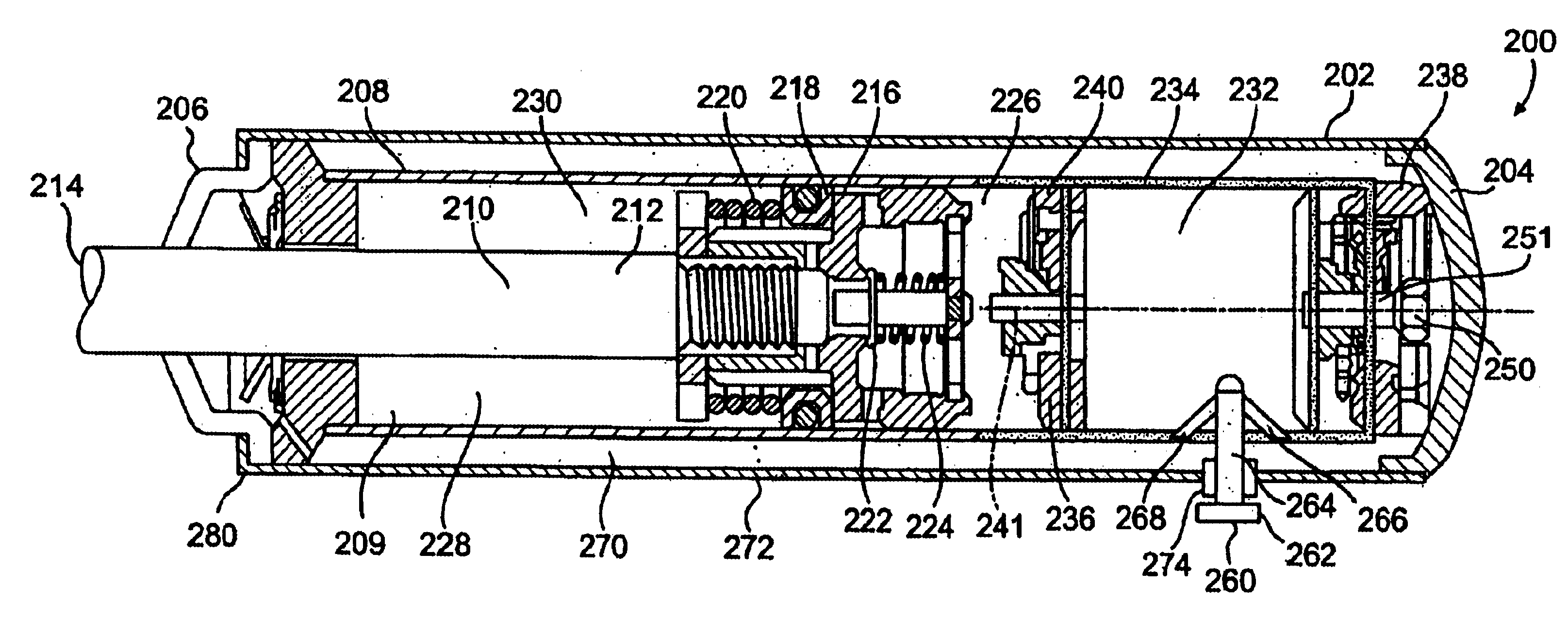
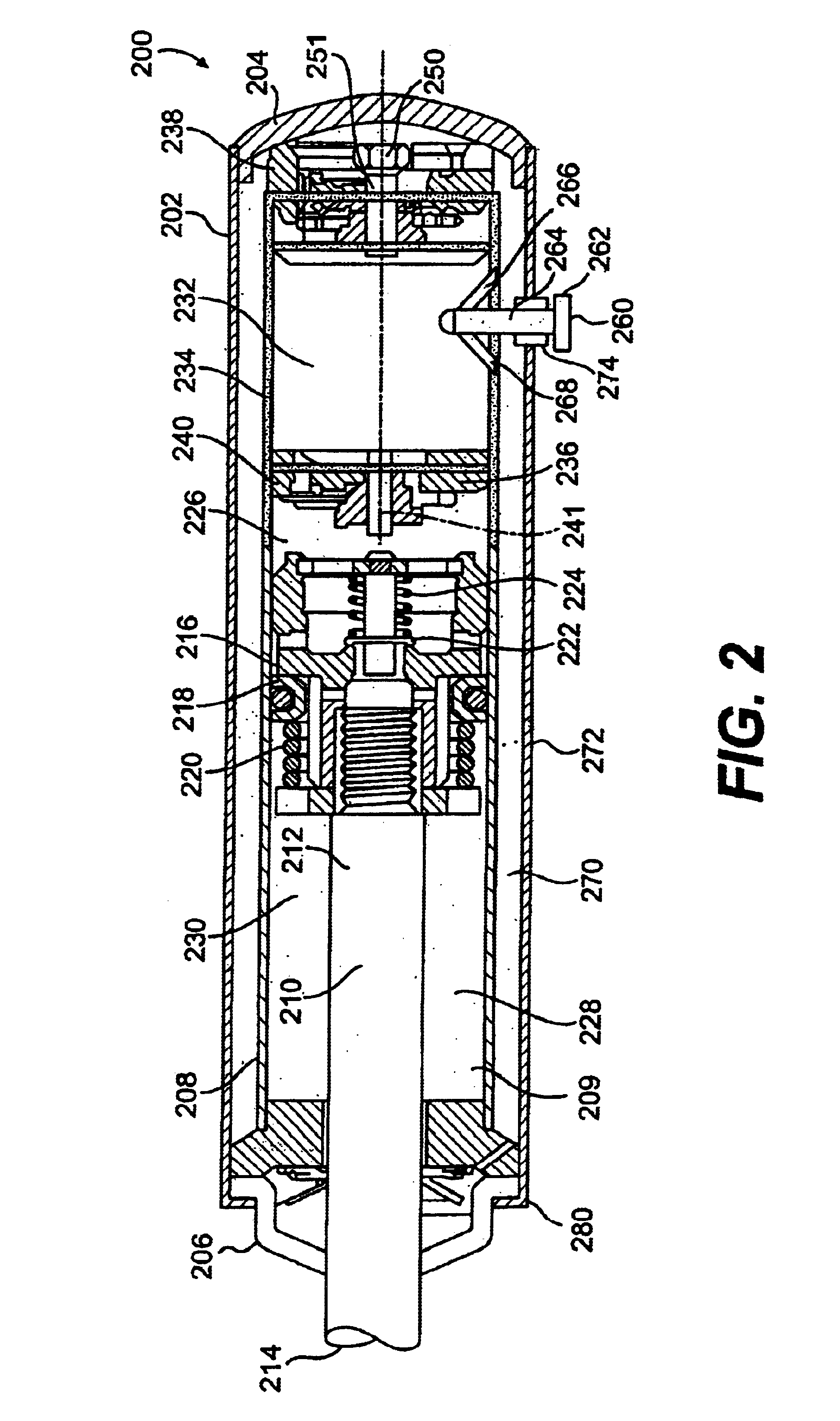
A shock absorber includes a shock rod and piston which are disposed within a fluid chamber within a shock body. The piston separates the shock body fluid chamber into a compression fluid chamber and a rebound fluid chamber. A reservoir fluid chamber accommodates the entry of the shock rod into the fluid chamber as the shock absorber compresses under shock forces. The compression fluid chamber is in fluid communication with the reservoir fluid chamber through a third chamber or passage. A first valve may control passage of fluid from the compression fluid chamber into the passage. Second and third valves may be disposed within the passage in parallel with each other and in series with the first valve. The third valve may include an easily accessible knob disposed outside the shock body.

Description

FIELD OF THE INVENTIONThe field of the present invention relates to shock absorbers that include a piston and shock rod assembly that move within a fluid containing shock housing.BACKGROUND OF THE INVENTIONShock absorbers are widely used in the suspension systems of recreational vehicles such as snowmobiles and all terrain vehicles. Shock absorbers dampen shocks experienced when the recreational vehicle travels over rough terrain. Shock absorbers are typically mounted between a vehicle component that moves in relation to the chassis and the chassis itself. Shock absorbers are often used in combination with a spring assembly which may or may not be integrated with the shock absorber. In a snowmobile, shock absorbers are typically positioned between the chassis and the slide frame around which an endless track rotates to propel the vehicle. The shock absorber(s) allow the slide frame to compress towards the chassis at a controlled rate. In the case of an all terrain vehicle, the shock...

Claims


Application Information

Patent Timeline
Patent Type & Authority Patents(United States)
IPC IPC(8): F16F9/44F16F9/00F16F9/06F16F9/18
CPCF16F9/44F16F9/062
Inventor LEMIEUX, RENE
Owner BOMBARDIER RECREATIONAL PROD INC
Learn More