Worm driven ball screw actuator for traction clutches
a technology of worm-driven ball screw actuator and traction clutch, which is applied in mechanical actuated clutches, transportation and packaging, and gearing. it can solve the problems of system cost prohibitive in some four-wheel drive vehicle applications
- Summary
- Abstract
- Description
- Claims
- Application Information
AI Technical Summary
Benefits of technology
Problems solved by technology
Method used
Image

Examples
case 22
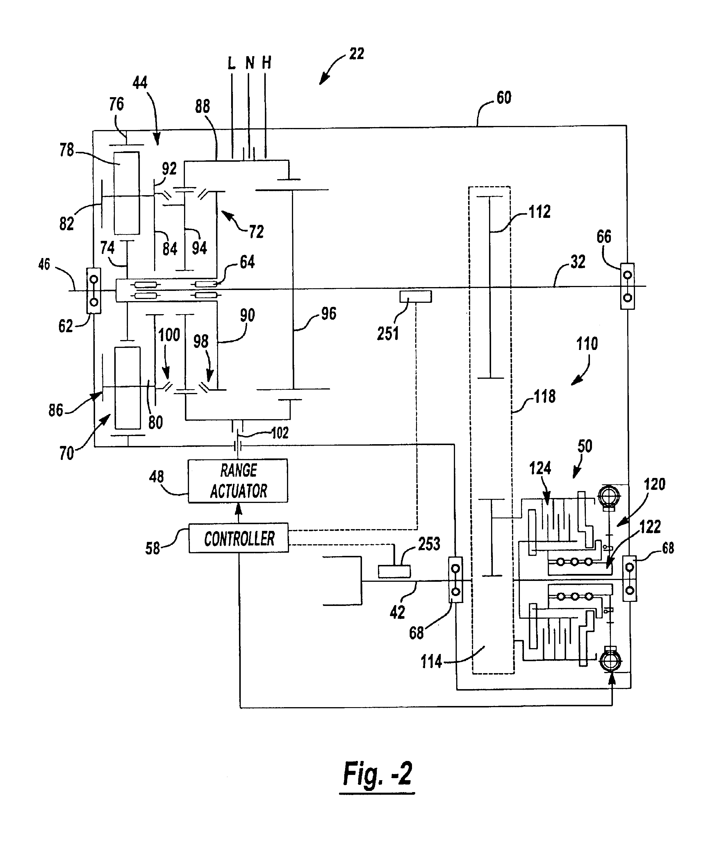
Transfer case 22 is shown schematically in FIG. 2 to include a housing 60 from which input shaft 46 is rotatably supported by bearing assembly 62. Input shaft 46 is adapted for connection to the output shaft of transmission 20. Rear output shaft 32 is also shown rotatably supported between input shaft 46 and housing 60 via bearing assemblies 64 and 66 while front output shaft 42 is rotatably supported from housing 60 by a pair of laterally-spaced bearing assemblies 68. Range clutch 44 is shown to include a planetary gearset 70 and a synchronized range shift mechanism 72. Planetary gearset 70 includes a sun gear 74 fixed for rotation with input shaft 46, a ring gear 76 fixed to housing 60, and a set of planet gears 78 rotatably supported on pinion shafts 80 extending between front and rear carrier rings 82 and 84, respectively, that are interconnected to define a carrier 86. Planetary gearset 70 functions as a two-speed reduction unit which, in conjunction with a sliding range sleeve...
case 300
Transfer case 300 includes a planetary gear set 305 interconnecting the vehicle transmission and a rear output shaft 306. Planetary gear set 305 includes an input shaft 308, a sun gear 310 and a carrier 312 rotatably supporting a plurality of planet gears 314. Clutch 302 may also be described as a direct clutch. Direct clutch 302 is normally applied to interconnect input shaft 308, sun gear 310 and carrier 312 such that rear output shaft 306 rotates at the same speed as input shaft 308. Direct clutch 302 is applied during high range operation and released by electrically signaling a clutch actuator 318. Because approximately 90 percent of vehicle operation occurs in the high range mode, electrical power consumption is minimized by constructing direct clutch 302 as a normally applied clutch.
Clutch 303 functions as a brake to selectively couple a ring gear 322 of planetary gear set 305 to the housing. Brake 303 is normally released and selectively applied by electrically signaling a b...
case 22 ′
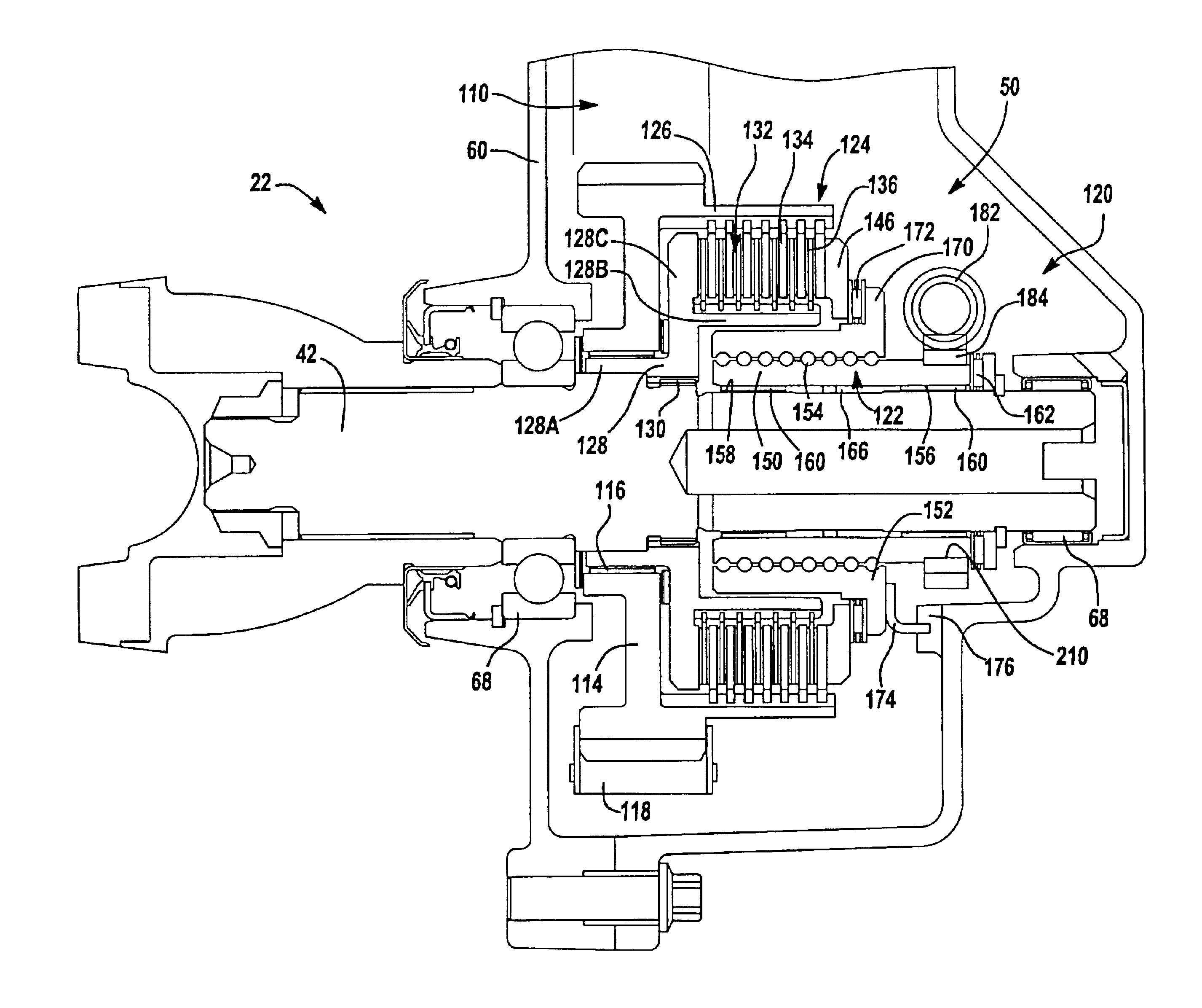
Transfer case 22′ further includes a biasing clutch 50′ having a multi-plate clutch assembly 124′ and a mode actuator 52′ (FIG. 6) having a clutch actuator 120′. Clutch assembly 124′ includes a drum 126′ fixed for rotation with first sprocket 112′, a hub 128′ fixed for rotation with rear output shaft 32′, and a multi-plate clutch pack 132′ operably disposed therebetween. Clutch actuator 120′ includes an electric motor that can be energized for controlling the movement of a ball screw operator relative to clutch pack 132′.
PUM
 Abstract
Description
Claims
Application Information
 - Generate Ideas
- Intellectual Property
- Life Sciences
- Materials
- Tech Scout
- Unparalleled Data Quality
- Higher Quality Content
- 60% Fewer Hallucinations
Browse by: Latest US Patents, China's latest patents, Technical Efficacy Thesaurus, Application Domain, Technology Topic, Popular Technical Reports.
© 2025 PatSnap. All rights reserved.Legal|Privacy policy|Modern Slavery Act Transparency Statement|Sitemap|About US| Contact US: help@patsnap.com