

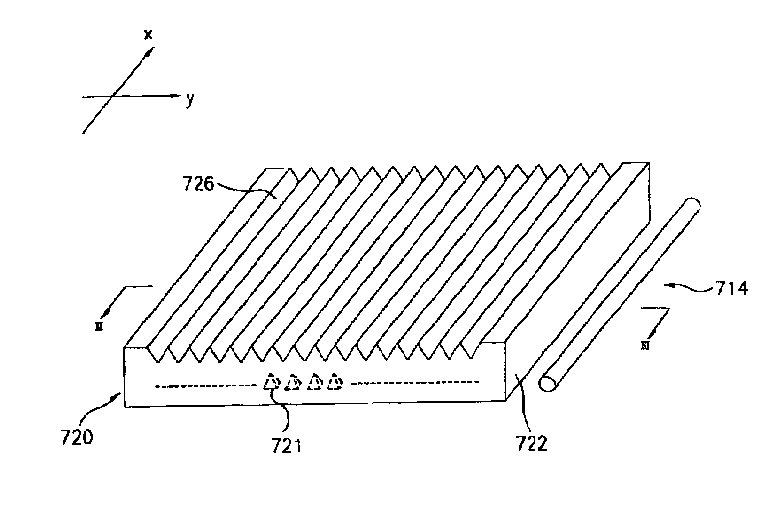
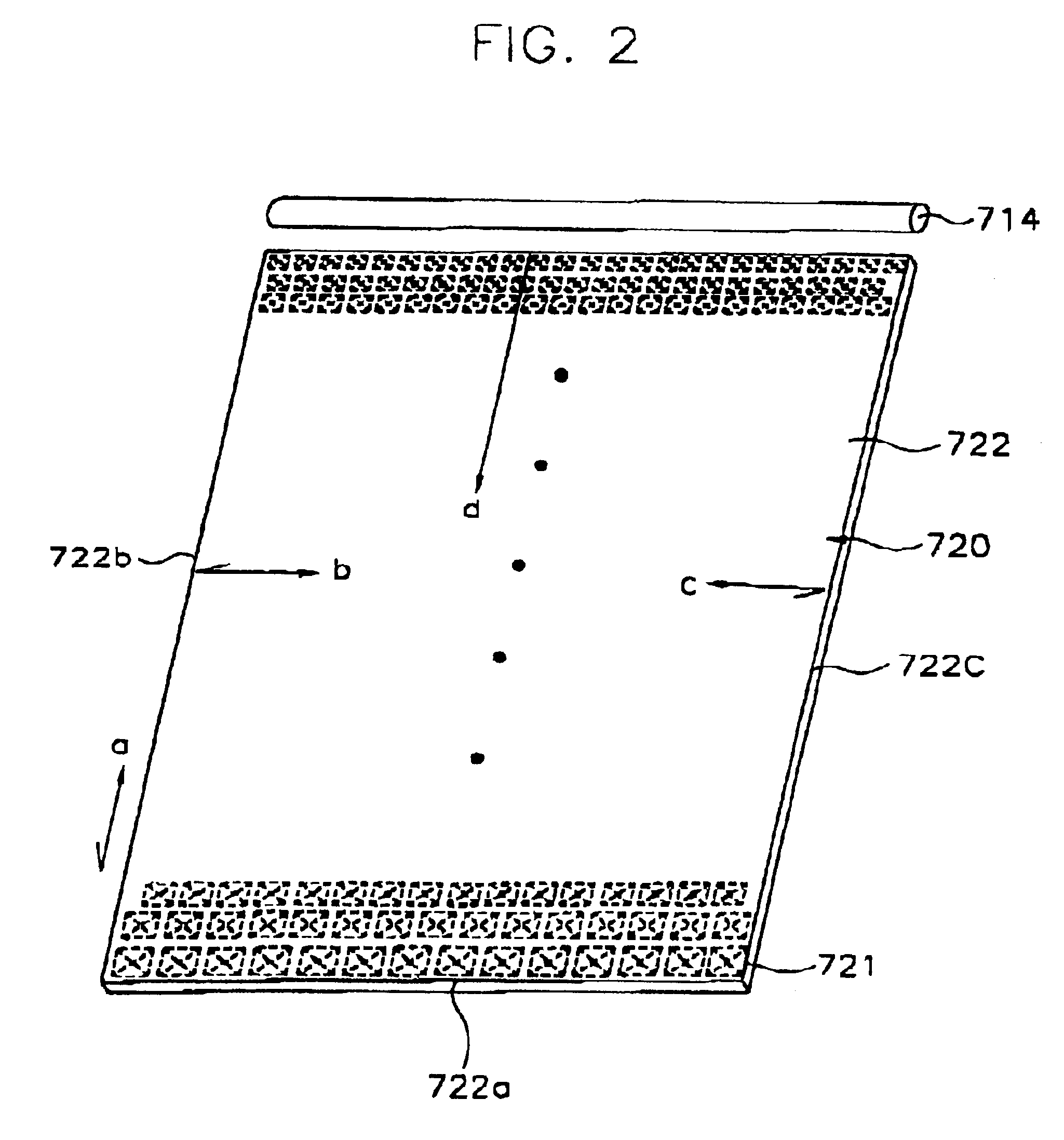
Light guide plate with trigonal recesses
a technology of light guide plate and trigonal recess, which is applied in the direction of lighting and heating apparatus, instruments, mechanical equipment, etc., can solve the problems of increasing electricity consumption, heavy weight of light crystal display device, and inability to display images in the dark, so as to increase the usage efficiency of light, enhance the brightness of light, and reduce the consumption of electricity
- Summary
- Abstract
- Description
- Claims
- Application Information
AI Technical Summary
Benefits of technology
Problems solved by technology
Method used
Image

Examples
Embodiment Construction
Hereinafter, a backlight assembly and a liquid crystal display device using thereof according to perferred embodiment of the present invention will be described in detail with reference to the accompanying drawings.
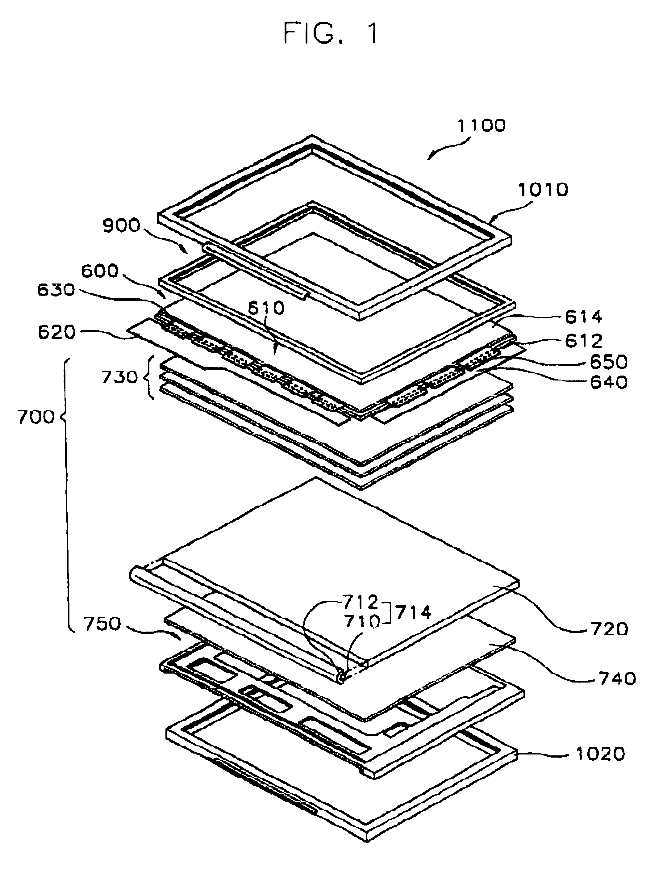
FIG. 1 is an exploded perspective view showing a liquid crystal display device according to an embodiment of the present invention.
Referring to FIG. 1, the liquid crystal display device 1100 generally includes a front case 1010 and a rear case 1020, a top chassis 900, a liquid crystal display panel assembly 600 and a backlight assembly.
Firstly, the liquid crystal display panel assembly 600 comprises a thin film transistor substrate 612, a color filter substrate 614, liquid crystals (not shown), data printed circuit board 620, flexible printed circuits 630 and 650, and gate printed circuit board 640 for operating the liquid crystal display panel.
Particularly, the thin film transistor substrate 612 is a transparent glass substrate on which thin film transistors respectively...
PUM
 Abstract
Description
Claims
Application Information