Low-loss resonator and method of making same

a low-loss, resonator technology, applied in the field of electromagnetically resonators, can solve the problems of intrinsic loss of energy, incomplete confinement, total internal reflection, etc., and achieve the effect of reducing or eliminating radiation loss

Inactive Publication Date: 2005-02-08
CAMBRIUS
View PDF5 Cites 4 Cited by
  • Summary
  • Abstract
  • Description
  • Claims
  • Application Information

AI Technical Summary

Benefits of technology

In accordance with one embodiment of the invention there is provided a method of making a low-loss electromagnetic wave resonator structure. The method includes providing a resonator structure, the resonator structure including a confining device and a surrounding medium. The resonator structure supports at least one resonant mode, the resonant mode displaying a near-field pattern in the vicinity of said confining device and a far-field radiation pattern away from the confining device. The surrounding medium supports at least one radiation channel into which the resonant mode can couple. The resonator structure is specifically configured to reduce or eliminate radiation loss from said resonant mode into at least one of the radiation channels, while keeping the characteristics of the near-field pattern substantially unchanged.

Problems solved by technology

Total internal reflection, or index confinement, on the other hand, is an incomplete confining mechanism.
If a resonator is constructed using these incomplete confining mechanisms, since a resonant mode is made up of a linear combination of components with all possible wavevectors, part of the electromagnetic energy will inevitably leak out into the surrounding media, resulting in an intrinsic loss of energy.

Method used


Image

  • Low-loss resonator and method of making same
  • Low-loss resonator and method of making same
  • Low-loss resonator and method of making same

Examples


Embodiment Construction

In accordance with the invention, a method of improving the radiation pattern of a resonator is provided. The method is fundamentally different from all the prior art as described above. The method relies upon the relationship of the radiation Q to the far-field radiation pattern. By designing the resonator structure properly, it is possible to affect the far-field radiation pattern, and thereby increase the radiation Q.

The general purpose of the method of the invention is to design electromagnetic wave resonators with low radiative energy losses. The rate of loss can be characterized by the quality factor (Q) of the resonator. One can determine the amount of radiation by integrating the energy flux over a closed surface far from the resonator. Thus, from the knowledge of the radiation pattern in the far field, it is possible to determine the resonator Q.

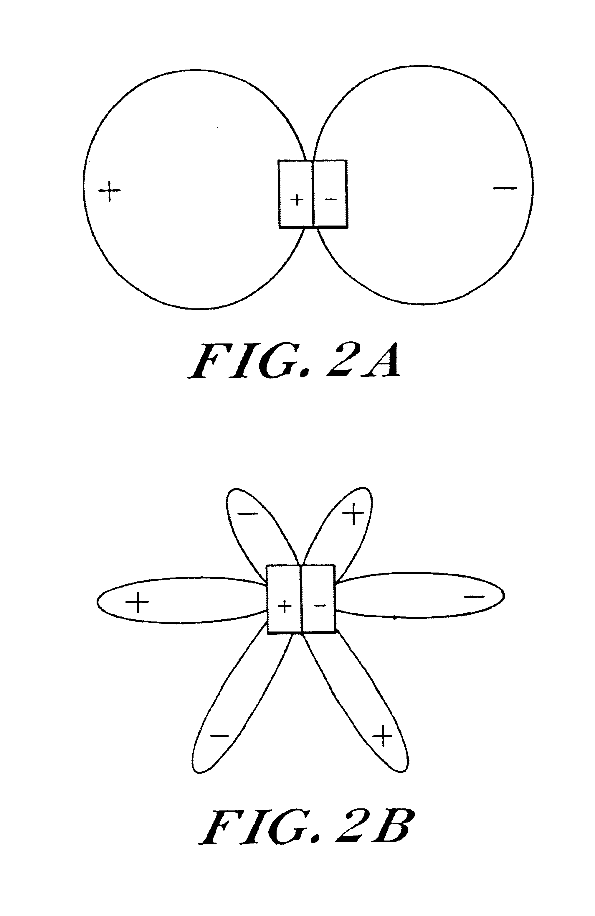
The radiation field can be broken down into radiation into different channels in the far field into which radiation can be emitted...


PUM


Abstract

A method of making a low-loss electromagnetic wave resonator structure. The method includes providing a resonator structure, the resonator structure including a confining device and a surrounding medium. The resonator structure supporting at least one resonant mode, the resonant mode displaying a near-field pattern in the vicinity of said confining device and a far-field radiation pattern away from the confining device. The surrounding medium supports at least one radiation channel into which the resonant mode can couple. The resonator structure is specifically configured to reduce or eliminate radiation loss from said resonant mode into at least one of the radiation channels, while keeping the characteristics of the near-field pattern substantially unchanged.

Description

BACKGROUND OF THE INVENTIONThe invention relates to the field of low-loss resonators.Electromagnetic resonators spatially confine electromagnetic energy. Such resonators have been widely used in lasers, and as narrow-bandpass filters. A figure of merit of an electromagnetic resonator is the quality factor Q. The Q-factor measures the number of periods that electromagnetic fields can oscillate in a resonator before the power in the resonator significantly leaks out. Higher Q-factor implies lower losses. In many devices, such as in the narrow bandpass filtering applications, a high quality factor is typically desirable.In order to construct an electromagnetic resonator, i.e., a cavity, it is necessary to provide reflection mechanisms in order to confine the electromagnetic fields within the resonator. These mechanisms include total-internal reflection, i.e. index confinement, photonic band gap effects in a photonic crystal, i.e., a periodic dielectric structure, or the use of metals. ...

Claims


Application Information

Patent Timeline
Patent Type & Authority Patents(United States)
IPC IPC(8): H01P7/00
CPCH01P7/00H01P1/2005
Inventor MEKIS, ATTILAFAN, SHANHUIJOANNOPOULOS, JOHN D.VILLENEUVE, PIERRE
Owner CAMBRIUS
Why Eureka
Try Eureka