Reinforcing system for stackable retaining wall units

a technology of retaining wall and unit, applied in mining structures, excavations, artificial islands, etc., can solve the problems of time-consuming and laborious ultimate interconnection operation, less than convenient interconnection,

Inactive Publication Date: 2005-02-15
ALLAN BLOCK CORPORATION
View PDF41 Cites 27 Cited by
  • Summary
  • Abstract
  • Description
  • Claims
  • Application Information

AI Technical Summary

Benefits of technology

Therefore, it is a primary object of the present invention to provide an improved interconnection between individual blocks in a retaining wall structure and a remotely positioned or disposed stable anchoring assembly.

Problems solved by technology

Little, if any, length adjustment has been possible in the coupling means, thereby making the interconnection less than convenient.
As such, the ultimate interconnecting operation can be time consuming due to the necessity of configuring coupling means to fit the block wall.

Method used


Image

  • Reinforcing system for stackable retaining wall units
  • Reinforcing system for stackable retaining wall units
  • Reinforcing system for stackable retaining wall units

Examples


Embodiment Construction

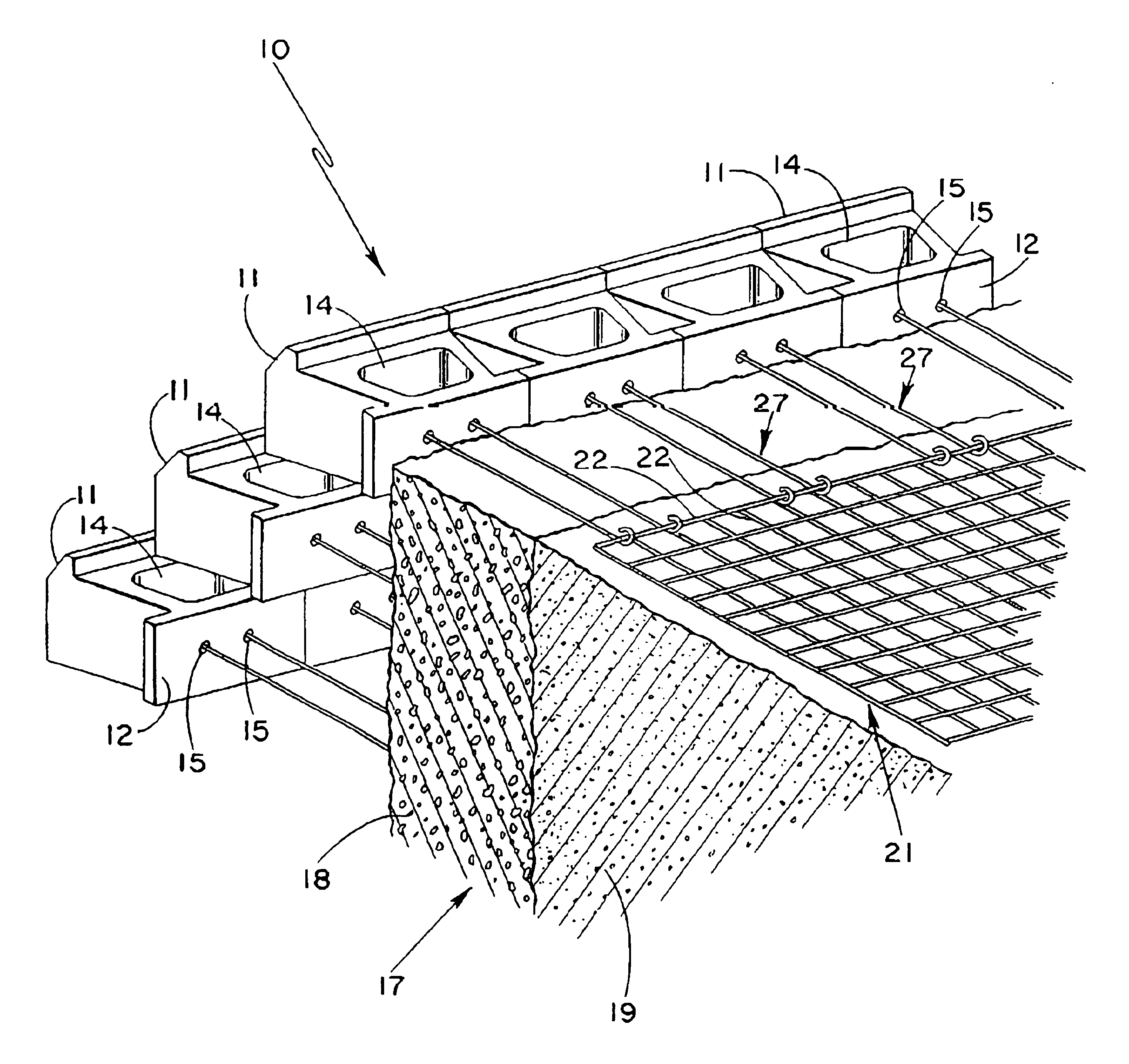
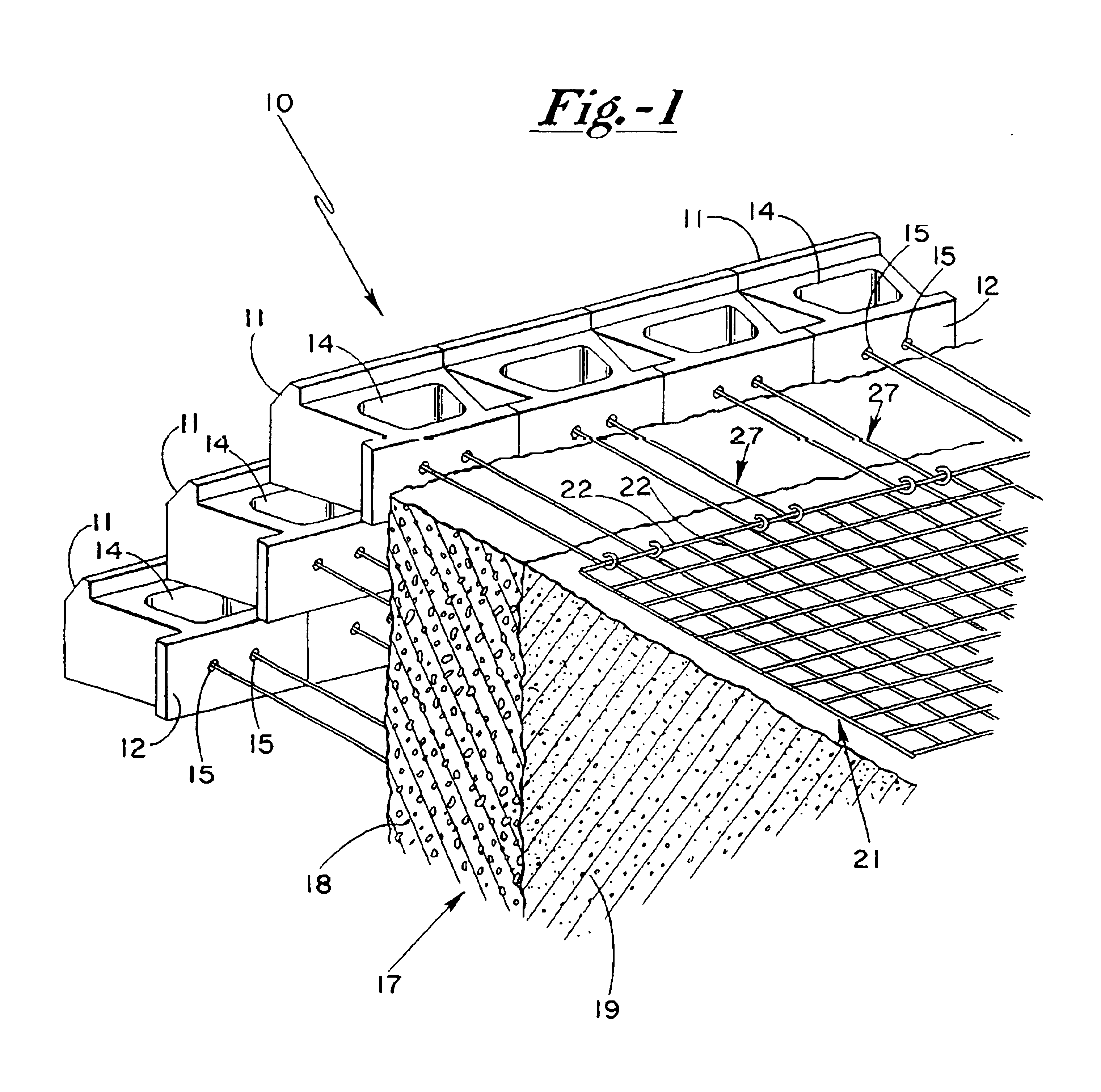
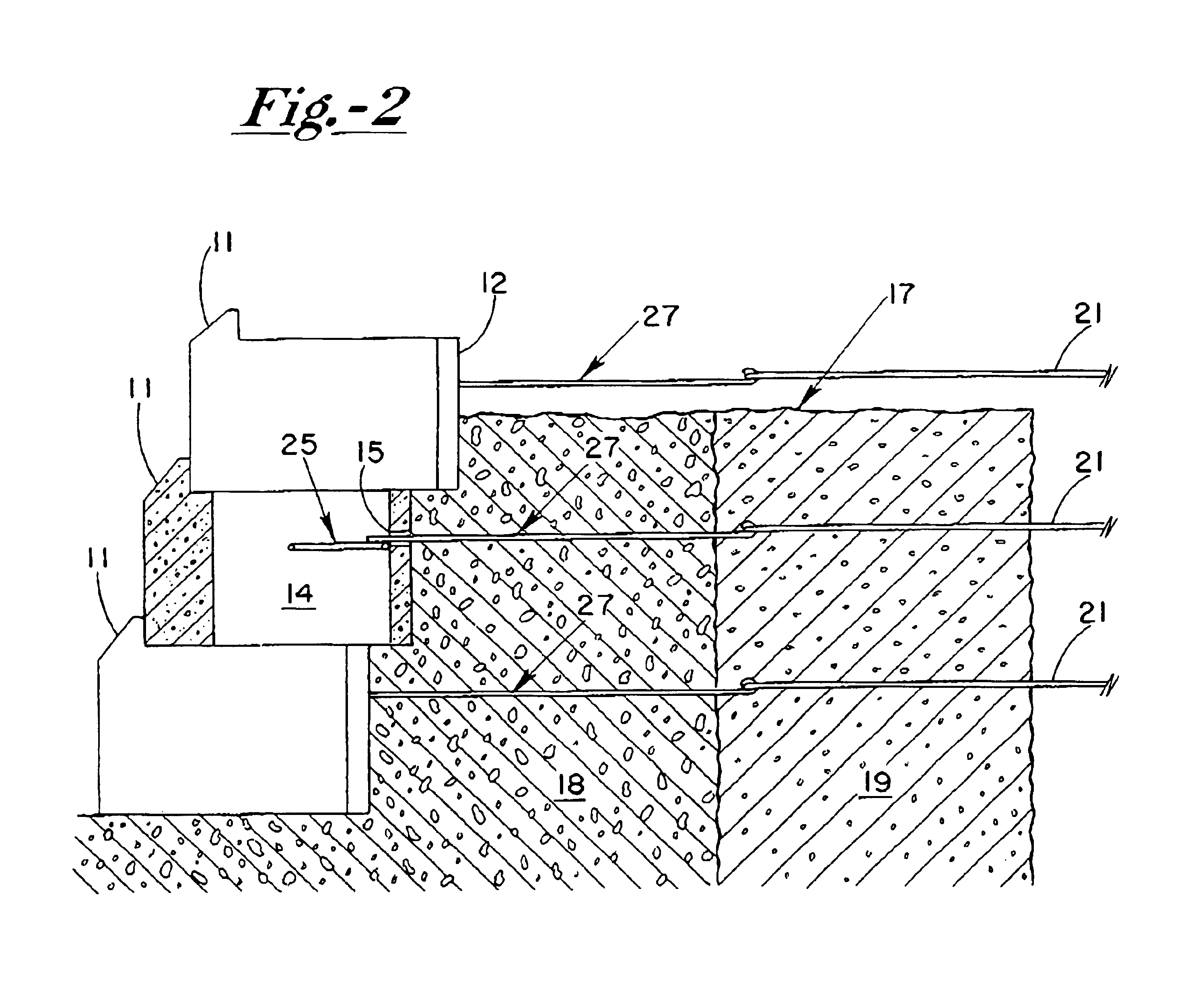
In accordance with one preferred embodiment of the present invention, and with particular attention being directed to FIG. 1 of the drawings, the stabilized retaining structure generally designated 10 comprises a plurality of individual blocks 11-11 which are arranged in a plurality of superimposed rows to form a stacked array. Each of the blocks 11 has a rear surface 12 with a hollow core 14 being formed in at least selected of blocks 11. Retaining wall blocks of this configuration and / or form are known in the art.

Blocks 11 are provided with an access bore 15 which extends through the block from the rear surface to the surfaces of the wall comprising the hollow core. As further indicated in FIG. 1, a rock and earthen fill such as is illustrated generally at 17 is in contact with the rear surfaces 12 of the blocks 11, with fill 17 comprising a pair of individual or separate layers. The first layer 18 positioned adjacent wall 10 is preferably clean granular backfill, such as clean cr...


PUM


Abstract

A stablized retaining wall structure comprising concrete blocks stacked in an array of superimposed rows, and with a stable anchoring assembly being in restraining contact with selected blocks. An access bore extends from the rear surface of the block to the surface of the wall comprising the hollow core. An earthen fill zone is arranged in spaced apart relationship to the rear surface of the wall and clean granular back-fill is interposed between the wall and the earthen fill zone. A keeper device is provided to couple selected wall blocks to the stable anchoring assembly, with the keeper device being configured to be restrainably held within the hollow core. An elongated fastener is coupled to the keeper device, with the fastener extending through the access bore and secured to the stable anchoring assembly.

Description

BACKGROUND OF THE INVENTIONThe present invention relates generally to an improved system for stabilizing retaining wall structures, and particularly retaining wall structures which comprise a plurality of individual blocks stacked in an array of superimposed rows. More particularly, the present invention relates to improved connector devices which provide and facilitate attachment between selected individual blocks and a remotely positioned stable anchoring assembly. By way of explanation, the stable anchoring assembly may typically be in the form of a geogrid, mesh, deadman, or the like, with the anchoring assembly normally being disposed in on-site soils which typically contain corrosion inducing salts and the like.Retaining walls are in general use for a wide variety of applications, including virtually any application where it is necessary to hold or retain earth to prevent erosion or undesired washing of a sloped surface or for general landscaping purposes. Examples of such app...

Claims


Application Information

Patent Timeline
Patent Type & Authority Patents(United States)
IPC IPC(8): E02D29/02
CPCE02D29/0241
Inventor BOTT, TIMOTHY A.
Owner ALLAN BLOCK CORPORATION
Why Eureka
Try Eureka