Method and apparatus to counterbalance intrinsic positive end expiratory pressure

a technology of intrinsic positive end expiratory pressure and counterbalance, which is applied in the direction of valve details, valve arrangement, operating means/releasing devices of valves, etc., can solve the problems of excessive peeping, inability of the lungs to return to vsub>r /sub>, and inability to use excessively

Inactive Publication Date: 2005-02-15
RESMED LTD
View PDF22 Cites 92 Cited by
  • Summary
  • Abstract
  • Description
  • Claims
  • Application Information

AI Technical Summary

Benefits of technology

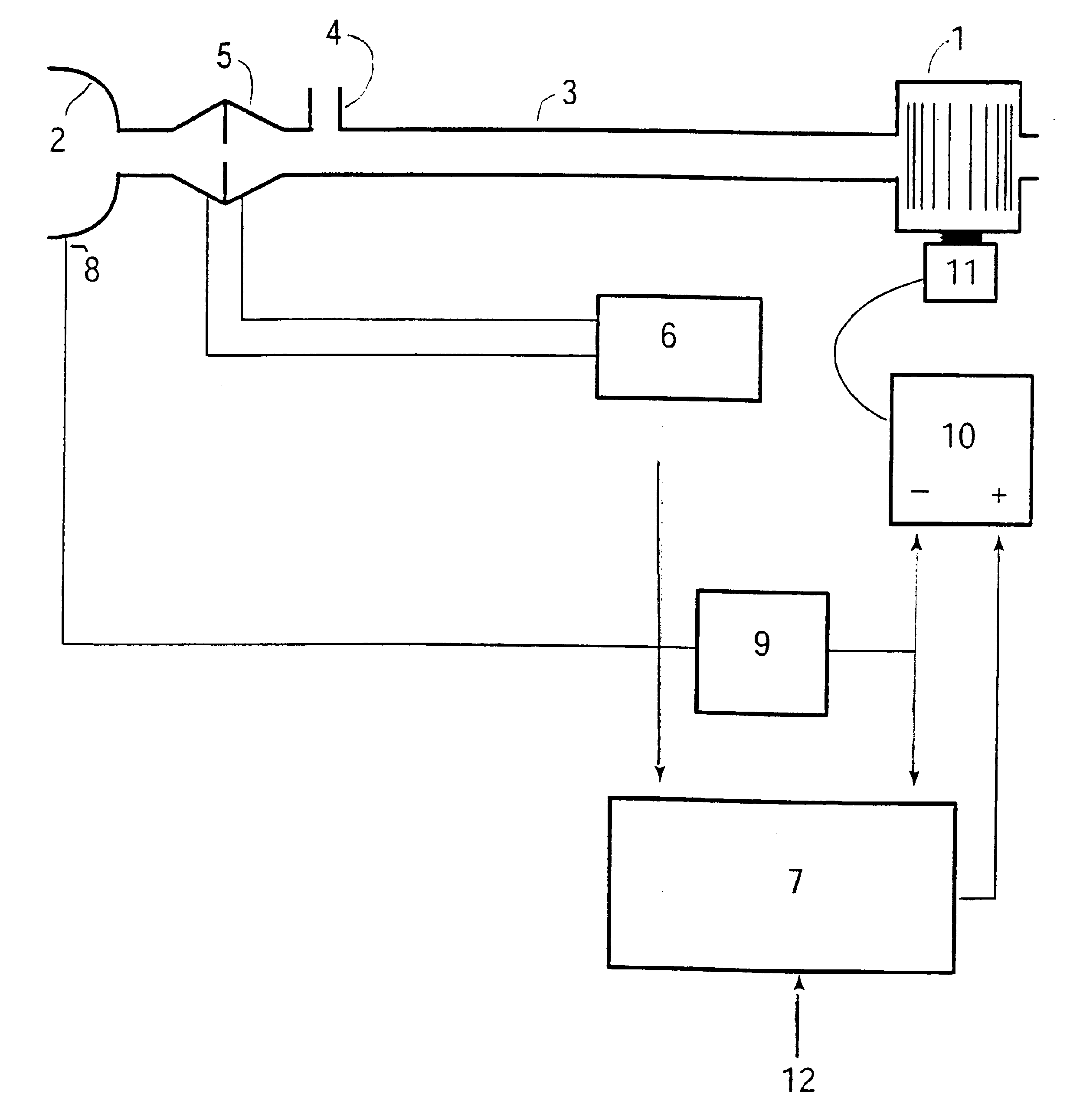
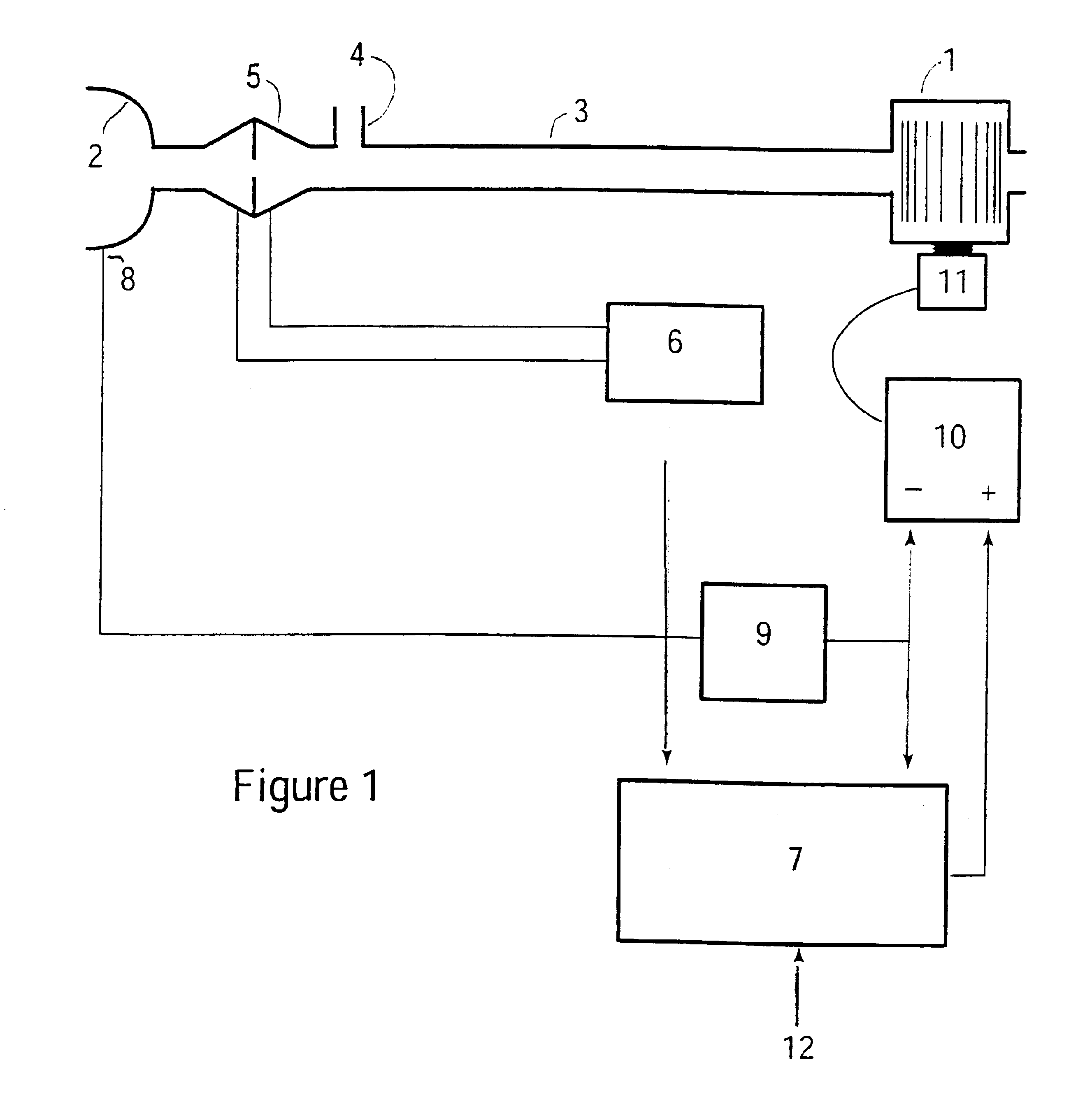
The present invention seeks to provide continuous and automatic adjustment of the expiratory pressure during ventilatory support, so as to substantially prevent dynamic airway compression and unload intrinsic PEEP with the smallest amount of external expiratory pressure.

Problems solved by technology

In patients with CAL, however, as a result of dynamic airway compression and fixed reduced expiratory flow rate, it is not possible for the lungs to return to VR in the time allowed before the start of the next inspiration.
A further undesirable effect of PEEPi is that during artificial mechanical ventilatory support, it interferes substantially with the triggering of the ventilator, causing patient-machine asynchrony.
Use of excessive PEEP, however, can be disadvantageous and even dangerous.
Excessive PEEP above and beyond PEEPi will cause yet further hyperinflation.
This will result in stiffening of the lung and chest wall, and an increase in the elastic work of breathing.
It will also cause reduced cardiac output, and can lead to barotrauma.
Further, the peak inspiratory airway pressure during ventilatory support cannot be arbitrarily increased without either exceeding the capacity of the ventilator, or reaching a pressure that is itself dangerous.
Finally, excessive external PEEP will also reduce the possible airway pressure excursion or headroom available for lung inflation.
These simple methods do not work for patients who are not sedated and paralyzed, and who are making spontaneous breathing efforts, because they do not take into account the patents' own respiratory muscle efforts.
One known method that is used with such patients requires a Muller manoeuvre (maximal inspiratory effort) during catheterization of the oesophagus and stomach, and is therefore completely unsatisfactory for repeated or continuous measurements in the ambulatory patient or the patient who is being treated at home long-term.
However, these references fail to describe servo-controlling of ventilation to increase or decrease PEEP so that the inspiratory arid expiratory conductances are approximately equal.
There is no known method or apparatus which can automatically or continuously control a ventilator or CPAP apparatus in conscious spontaneously breathing patients in order to prevent expiratory airflow limitation or to unload PEEPi in CAL.

Method used


Image

  • Method and apparatus to counterbalance intrinsic positive end expiratory pressure
  • Method and apparatus to counterbalance intrinsic positive end expiratory pressure

Examples


first embodiment

Two embodiments for deriving a measure of the degree of expiratory airflow limitation will now be considered. In the first embodiment, airway conductance during inspiration is compared with airway conductance during expiration, and a higher conductance during inspiration indicates expiratory airflow limitation. Airway conductance is calculated by superimposing on the instantaneous mask pressure a 4-Hz oscillation of amplitude 1 cmH2O, and measuring the component of the respiratory airflow signal at 4 Hz. The conductance may be calculated once for each half cycle of the 4-Hz oscillation. In order to identify inspiratory and expiratory halves of the respiratory cycle, the respiratory airflow is low-pass filtered to minimize the imposed 4-Hz oscillation, for example, by averaging measured respiratory airflow over a moving window of length 0.25 seconds. If the 4-Hz low-pass filtered flow is above a threshold such as 0.1 L / sec, it is taken to be the inspiratory half-cycle. Otherwise, it ...

second embodiment

In the second embodiment for deriving a measure of the degree of expiratory airflow limitation, the degree of expiratory flow limitation is calculated from the shape of the expiratory flow versus time curve. The expiratory portion of each breath is identified, for example, by taking expiration as the period where airflow is less than 0.1 L / sec. The mean expiratory airflow during the final 25% of expiratory duration is calculated, and divided by the peak expiratory airflow. For a subject without expiratory airflow limitation, this ratio will be close to zero, and less than a threshold such as 0.2, whereas for a subject with expiratory airflow limitation, it will be larger, for example, in the range 0.2 to 0.6, with higher values indicating more severe dynamic airway compression. Therefore, a second measure of the degree of expiratory airflow limitation is M2=(mean expiratory flow during last 25% of expiratory time) / (peak expiratory flow)−threshold, where the threshold is, for example...


PUM


Abstract

The invention prevents dynamic airway compression during ventilatory support of a patient. The respiratory airflow is determined by measurement or calculation, and a measure of the degree of dynamic airway compression is derived from the determined airflow. This measure is servo-controlled to be zero by increasing expiratory pressure if the measure of the degree of dynamic airway compression is large or increasing, and by reducing expiratory pressure if the measure of the degree of dynamic airway compression is small or zero.

Description

FIELD OF THE INVENTIONThis invention pertains to the field of ventilatory support for respiratory failure, particularly due to lung disease, and in particular to automatically providing sufficient end expiratory pressure to unload intrinsic positive end expiratory pressure (PEEPi).BACKGROUND OF THE INVENTIONSubjects with chronic airflow limitation (CAL) due, for example, to emphysema and chronic bronchitis, may require ventilatory assistance, particularly during periods of acute exacerbation, or routinely at night.Ventilatory support can reduce the work of breathing, reduce the sensation of breathlessness, and improve blood gases (oxygen and carbon dioxide levels). In subjects with CAL, most of the work of breathing is due to the high airway resistance. Approximately two thirds of this resistance is relatively fixed, and due to narrowing of the airways. However, of the order of one third of the resistance is due to dynamic airway compression during expiration. Dynamic airway compres...

Claims


Application Information

Patent Timeline
Patent Type & Authority Patents(United States)
IPC IPC(8): A61M16/00
CPCA61M16/00A61M16/0057A61M16/0069A61M2016/0036A61M2016/0039A61M2016/0021A61M16/0006A61M16/0858A61M16/024
Inventor BERTHON-JONES, MICHAELHALLETT, MICHAEL DAVID
Owner RESMED LTD
Why Eureka
Try Eureka