T-shaped cutter tool assembly with wear sleeve

Inactive Publication Date: 2005-02-15
KENNAMETAL INC
View PDF19 Cites 216 Cited by
  • Summary
  • Abstract
  • Description
  • Claims
  • Application Information

AI Technical Summary

Benefits of technology

Another objective of the invention is to design bit holders that have a preferential failing means that can be more quickly and less expensively manufactur

Problems solved by technology

Cutting tools are subjected to large torques and loads.
This rotation of the bit causes the holding surface of the bit holder to wear at an accelerated rate.
The bit holders become unusable after they wear causing the cutting bit to stop rotating or to fall out of the bit holder.
The bit holders take a significant amount of time to replace, typically either by blow torching off the old bit holder and welding a new bit holder onto a rotatable drum, or by mechanically removing the old bit holder mechanically fixing on a new bit holder.
Eventually these wear sleeves fail and must also be replaced.
Nonrotating wear sleeves tend to wear unevenly on upstream shoulder of the protective sleeve.
The holding and cutting equipment for such precision is costly and the manufacturing steps time consuming.
Slight deviations in the outside diameter of the sleeve and diameter of the bit holder bore affects the amount of interference and results in large variations in the amount of manual forc

Method used


Image

  • T-shaped cutter tool assembly with wear sleeve
  • T-shaped cutter tool assembly with wear sleeve
  • T-shaped cutter tool assembly with wear sleeve

Examples


Example

FIGS. 5 and 6 illustrate a second embodiment of the present invention. The second embodiment shows a standard well-known bit holder 36 for mounting the cutting tool. A wear sleeve 38 similar to the wear sleeve disclosed in the first embodiment and shown in FIG. 4 is inserted into a stepped bore aperture 44 similar in construction to the step bore illustrated in FIG. 3. The split ring design frictionally fixes the wear sleeve in position inside the bit holder aperture.

The shoulder of the wear sleeve in the second embodiment is also greater in thickness than prior art shoulders. Similar to the first embodiment the thick collar design extends the useful life of the wear sleeve.

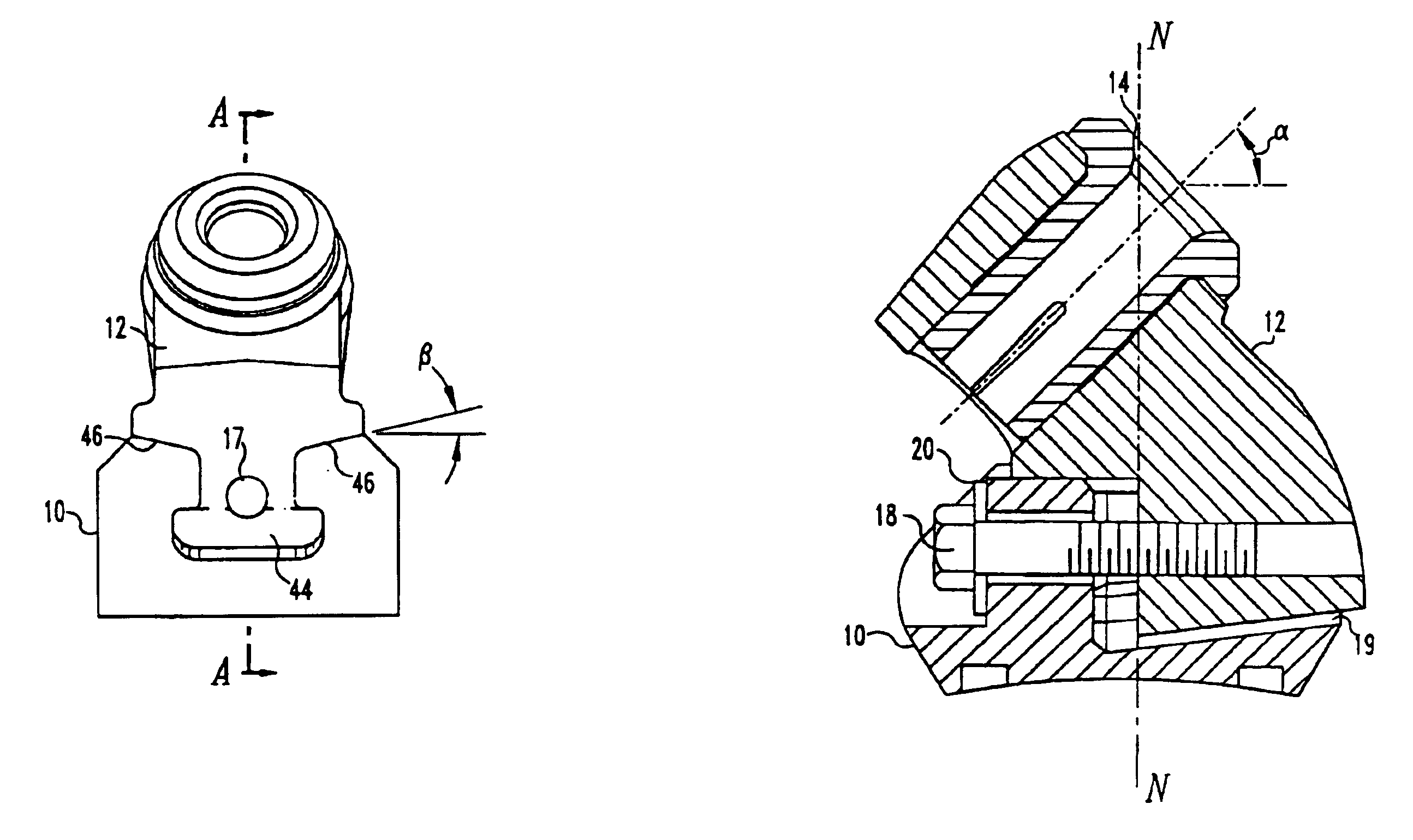
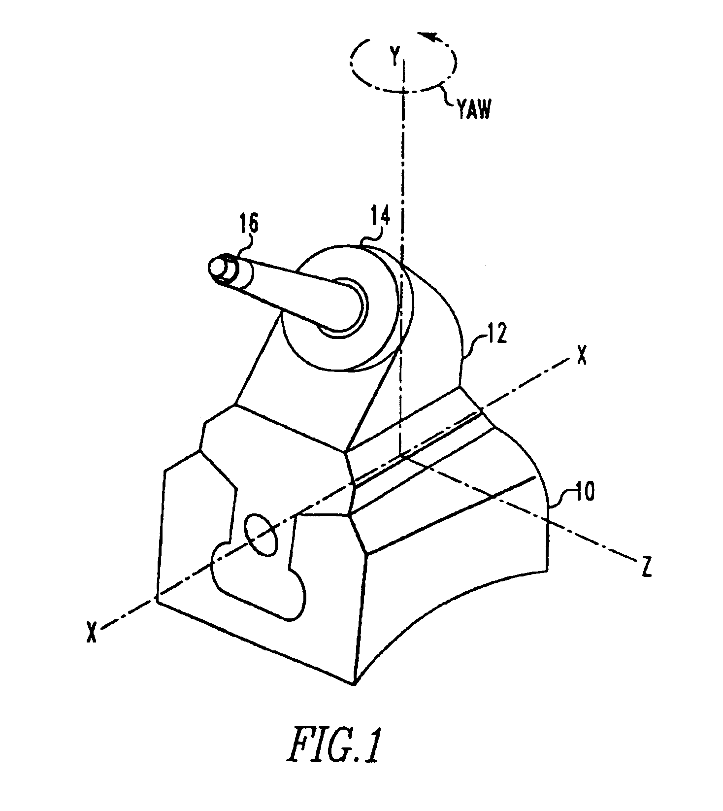
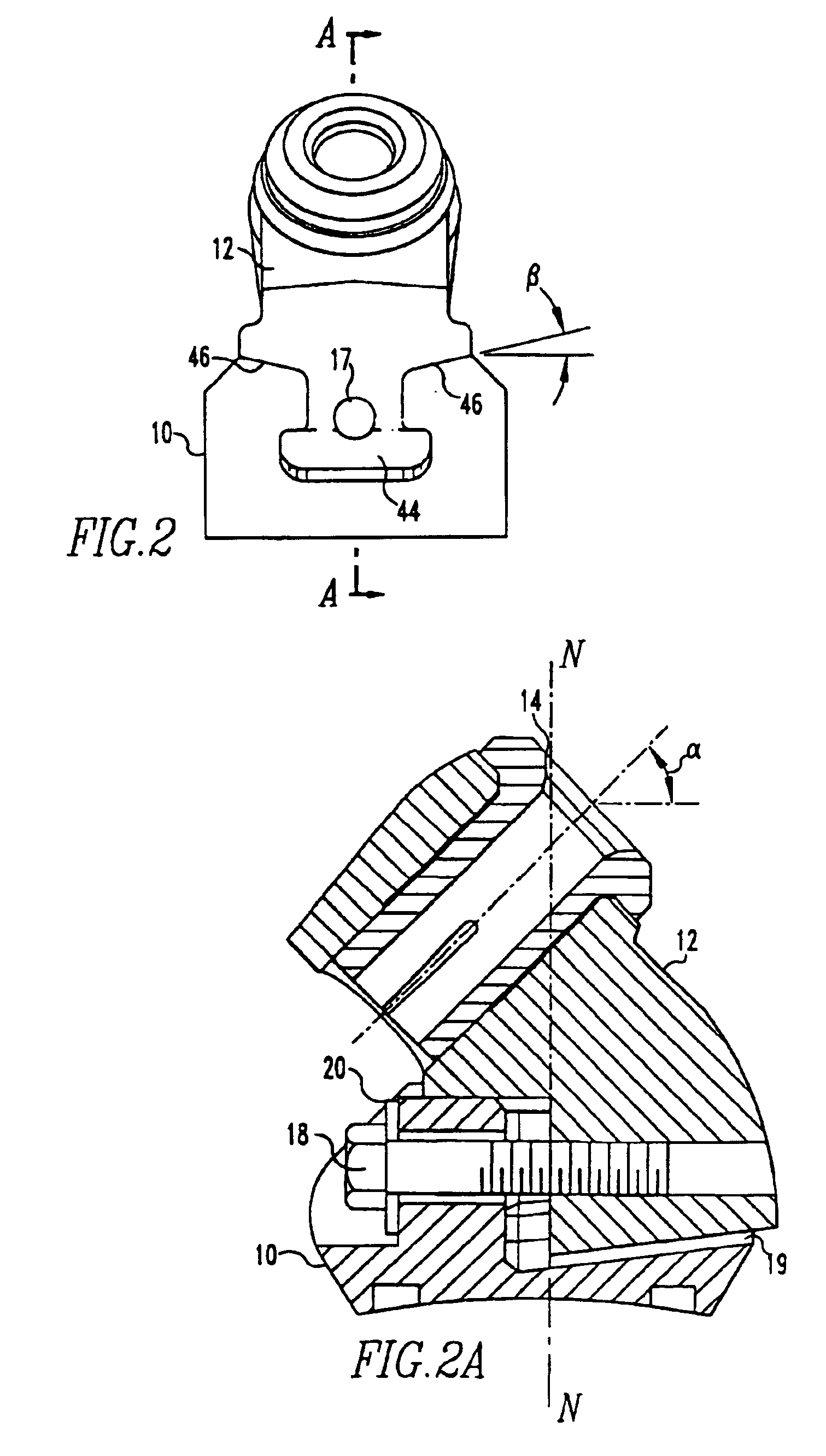
Yaw as shown in FIG. 1 is rotation about the central vertical axis of the support block, see the Y-axis. Rotation about the Y-axis occurs in the horizontal X-Z plane. Forces are applied to the cutting tool tip 16 during rotation of the pick into the earth's strata. The resultant forces applied to the cutting pick...

Example

FIG. 2 shows the front view of the first embodiment in which the support block groove 19 and T-shaped Key 44 are illustrated. The bit holder 12 rests on top of the support block on symmetric top surfaces 46 adjacent to the centrally located groove 19. The top surfaces 46 of the support block are oriented at an angle (beta) with respect to the horizontal. In the prior art these surfaces are angled at approximately 10 degrees to the horizontal. The present design includes an angle of at least 15 degrees. In one contemplated embodiment the top surfaces are angled at about 15 degrees. The bit holder has a surface that forms a complimentary angle with the top surface of the support block so that the bit holder makes uninterrupted contact with surface 46. This angle of inclination prevents back and forth movement along Z-axis. This inhibition of movement of the bit holder away from the Z-axis accordingly limits rotation about the Y axis. This reduction in yaw about the Y axis reduces the ...


PUM


Abstract

The wear sleeve in the present cutter tool assembly comprises a rearward split ring portion and an intermediate cylindrical ring portion adjacent a forward shoulder portion. The outer diameter of the wear sleeve intermediate portion and rearward split ring portion is uniform. The wear sleeve is inserted into the bit holder's stepped bore aperture. The split ring portion is radially compressed by the smaller diameter rearward end as the sleeve is hammered and axially displaced into the bit holder. The split ring portion forms frictional contact with the opposite end portion of the aperture. The wear sleeve friction fit can be easily removed manually in the field. The bit holder and cooperating support block are designed to limit the amount of relative yaw between the two members during operation to reduce the overall wear there between. The cutter tool assembly includes a groove having side surfaces that are inclined at least 15 degrees with respect to the horizontal axis and the cutting bit is positioned more aft of the central axis of the support block than prior art designs.

Description

FIELD OF THE INVENTIONThe invention relates to a readily replaceable protective wear sleeve for a bit holder.BACKGROUND OF THE INVENTIONThe present invention relates to mining and construction cutting bits and holders, the holders being attached to a rotating cutting drum. The holder includes a replaceable wear sleeve that receives the cutting bit tool.Cutting tools are subjected to large torques and loads. The cutting bits generally need to be replaced daily. Since the cutting tools require routine maintenance there is a preference and need in the industry to construct a cutting tool assembly that is easily and quickly replaceable in the field.The holders are often designed to permit the cutting tool to rotate to avoid uneven wear of the bit tool holder and cutting bit. This rotation of the bit causes the holding surface of the bit holder to wear at an accelerated rate. The bit holders become unusable after they wear causing the cutting bit to stop rotating or to fall out of the bi...

Claims


Application Information

Patent Timeline
IPC IPC(8): E21C35/00E21C35/197
CPCE21C35/197
Inventor MONTGOMERY, JR., ROBERT H.
Owner KENNAMETAL INC
Why Eureka
Try Eureka