Ergonomically friendly orbital sander construction

Inactive Publication Date: 2005-02-15
CHAO HAO CHIEN
View PDF43 Cites 42 Cited by
  • Summary
  • Abstract
  • Description
  • Claims
  • Application Information

AI Technical Summary

Benefits of technology

It is one object of the present invention to provide an improved orbital sander which has a relatively low height which contributes toward making the sander ergonomically friendly and wh

Problems solved by technology

In addition, in all prior orbital sanders, the abrasive dust enters the housing containing bearings which support the spindle which carries the pad, thereby shortening the bearing life and also causing the pad to opera

Method used


Image

  • Ergonomically friendly orbital sander construction
  • Ergonomically friendly orbital sander construction
  • Ergonomically friendly orbital sander construction

Examples


Embodiment Construction

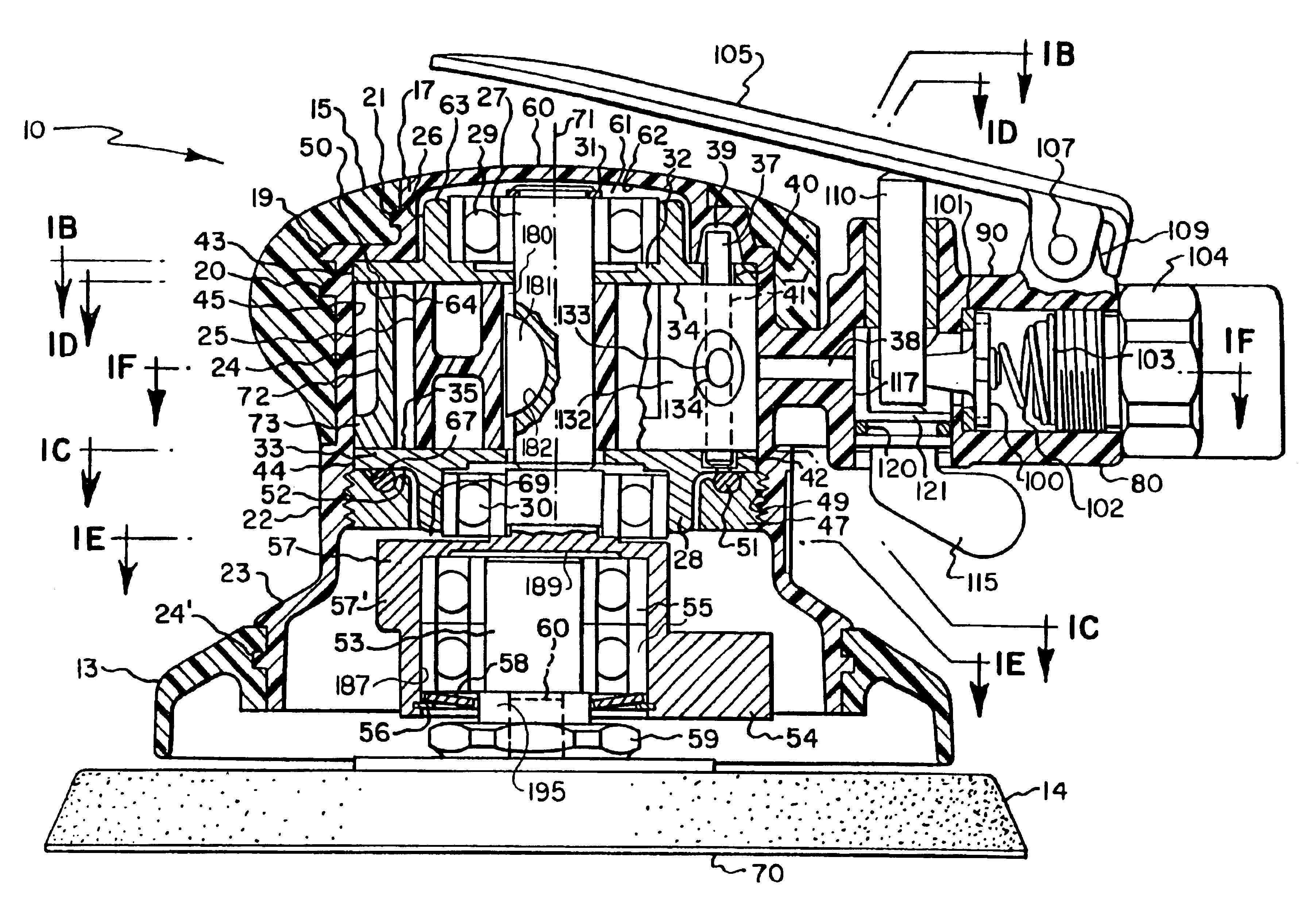
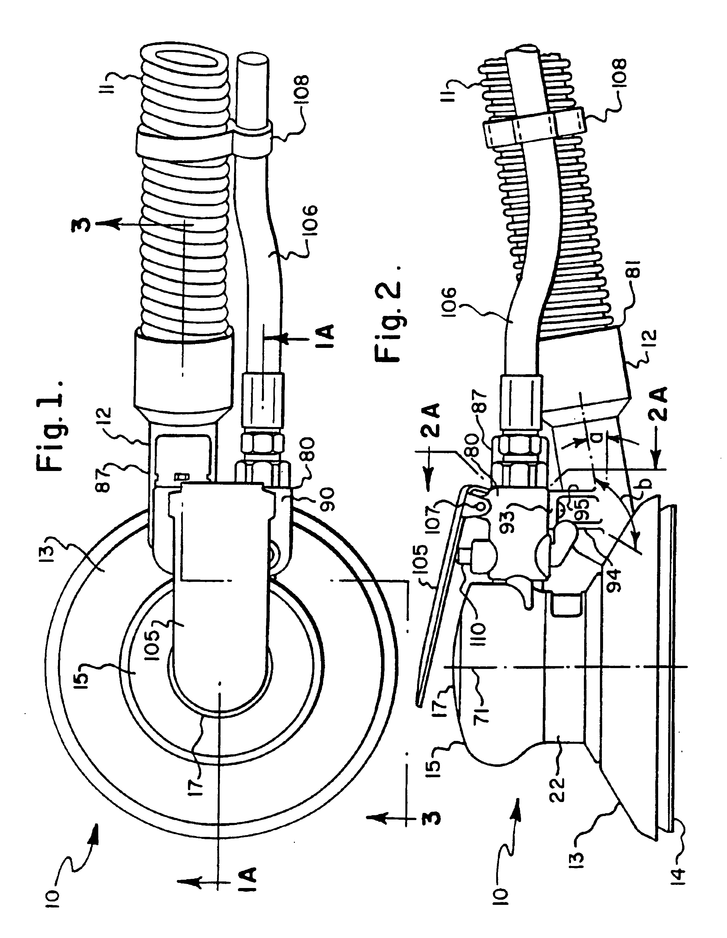
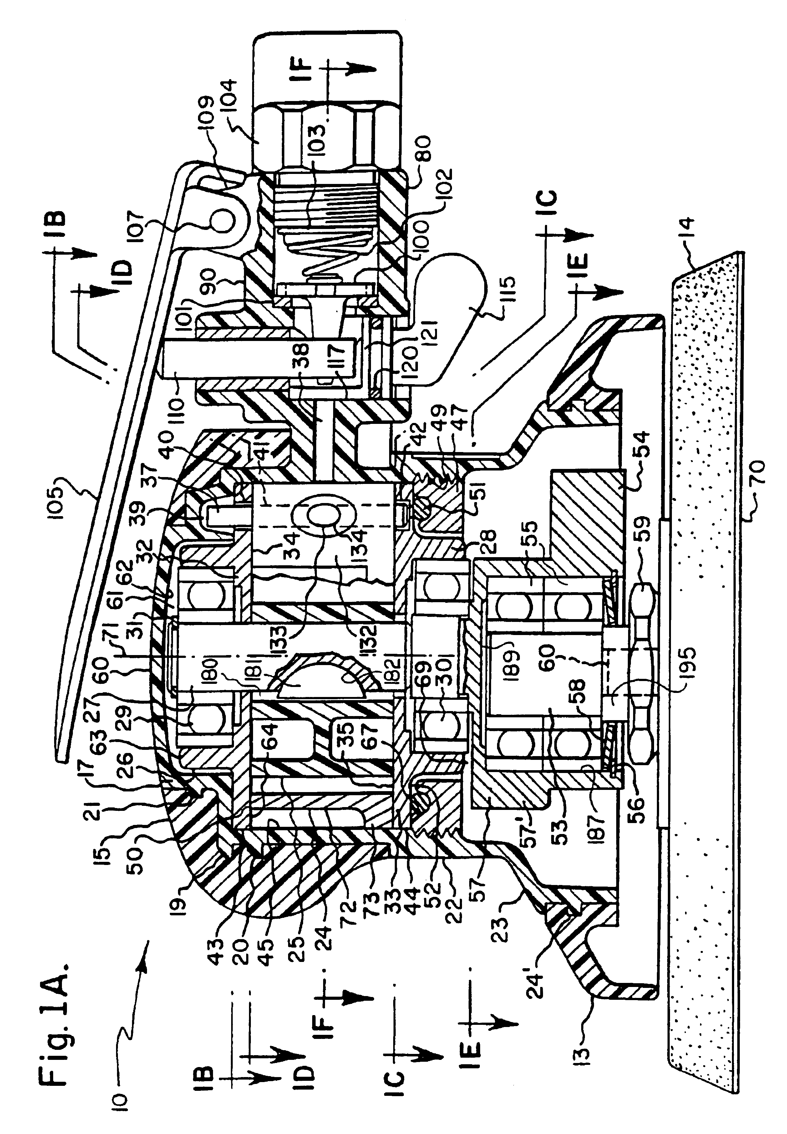
The present invention relates to an orbital sander which has a relatively low height and thus is ergonomically friendly, while also providing good columnar strength to maintain the pad in a close orbital plane and also permitting good orbital flexibility. Its low height is due in part to the compressed air motor which drives it, and this motor is the same that is used in the three previous types of random orbital sanders which are described hereafter. Its low height is also due to the use of a columnar connection between the housing in the pad which provides good columnar strength while providing good orbital flexibility.

The compressed air motor which is used in the orbital sander of the present invention is also used in the three basic types of random orbital sanders which are described hereafter. The first and most rudimentary type is the non-vacuum type which does not have any vacuum associated with it for the purpose of conveying away the dust which is generated during a sanding...


PUM


Abstract

A random orbital sander including a housing, a motor having a vertical axis in the housing, a pad coupled to the motor, a face on the pad extending substantially perpendicularly to the vertical axis, a shroud surrounding the pad, an opening in the shroud, and a dust discharge tube having an inner end in communication with the opening and an outer end on the dust discharge tube end extending at an acute angle to the face of the pad. An orbital sander wherein the pad is supported from the sander housing by columnar units located on opposite sides of the motor. A bore in the motor shaft conducts compressed air through the chamber housing the bearings which support the spindle which mounts the pad.

Description

STATEMENT REGARDING FEDERALLY SPONSORED RESEARCH OR DEVELOPMENTNot ApplicableBACKGROUND OF THE INVENTIONThe present invention relates to an improved ergonomically friendly surface-treating tool in which a flat surface of a pad engages the surface of a workpiece for the purpose of abrading or polishing it and more particularly to an improved orbital sander.By way of background, in operation, orbital sanders create forces at the sanding surface which are transmitted back to the operator's hand and arm through a lever which is the height of the orbital sander between the face of the sanding disc and the top of the casing at the vertical centerline of the sander. Therefore, if this height is as short as possible, the operator's effort in overcoming the forces produced at the face of the sanding disc are less than if the height was greater.In orbital sanders it is desirable that, in addition for the height of the tool being as small as possible, the connection between the housing and the...

Claims


Application Information

Patent Timeline
IPC IPC(8): B24B23/03B24B23/00B24B23/04B24B41/00B24B55/00B24B55/10F04C18/34F04C18/344
CPCB24B23/03B24B23/04F04C18/3441B24B55/105B24B41/007
Inventor HUBER, PAUL W.
Owner CHAO HAO CHIEN
Why Eureka
Try Eureka