
Self-wetting, dry-field bipolar electrodes for endoscopic surgery

Inactive Publication Date: 2005-02-15
ETHICON INC
View PDF5 Cites 34 Cited by
  • Summary
  • Abstract
  • Description
  • Claims
  • Application Information

AI Technical Summary

Problems solved by technology

A historic limitation of these devices has been their inability to cut tissue, which greatly limits their utility.
As the active electrode is completely exposed and unprotected, any error while placing or manipulating the device can result in unwanted damage to surrounding tissue.

Method used


Image

  • Self-wetting, dry-field bipolar electrodes for endoscopic surgery
  • Self-wetting, dry-field bipolar electrodes for endoscopic surgery
  • Self-wetting, dry-field bipolar electrodes for endoscopic surgery

Examples


Embodiment Construction

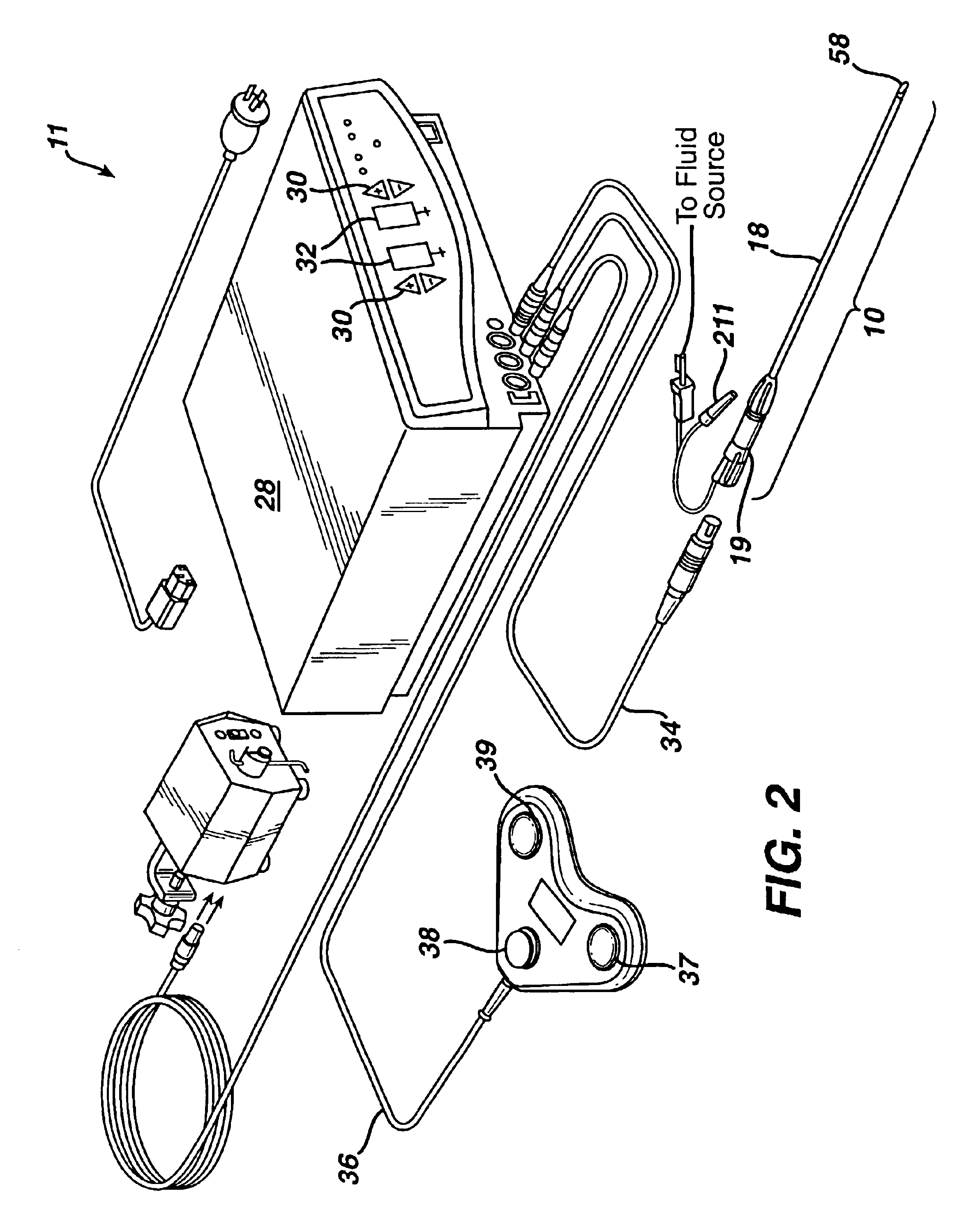
Referring now to FIGS. 2-5, an exemplary electrosurgical system and method for cutting, resecting, ablating or otherwise modifying tissue will now be described in detail. As shown in FIG. 2, an exemplary electrosurgical system 11 generally comprises an electrosurgical handpiece or probe 10 connected to a power supply 28 for providing high frequency voltage, and a fluid source (not shown) for supplying electrically conductive fluid, such as saline, to the probe. In addition, the electrosurgical system may include an endoscope (not shown) with a fiber optic head light for viewing the surgical site. The endoscope may be integral with probe 10, or it may be part of a separate instrument. The system 11 may also include a vacuum source (not shown) for coupling to a suction lumen or tube 211 in the probe for aspirating the target site.

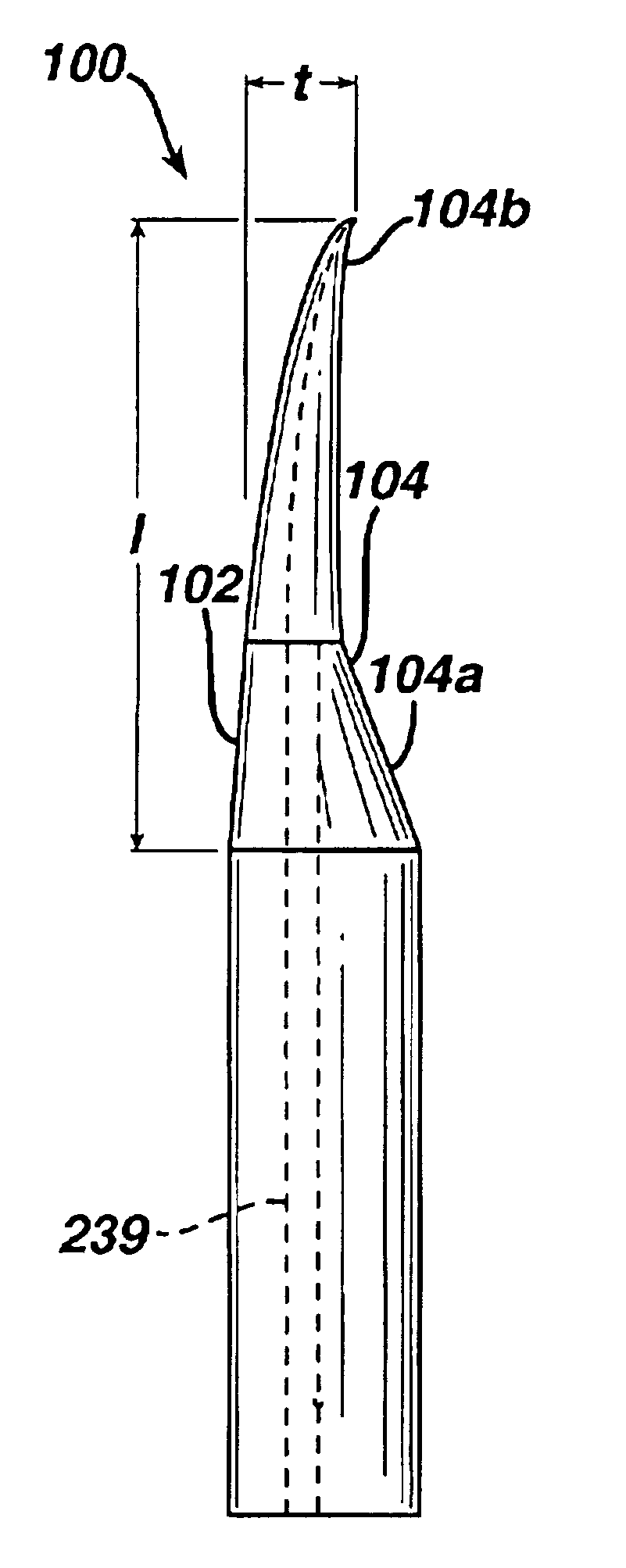
As shown, probe 10 generally includes a proximal handle 19 and an elongate shaft 18 having one or more active electrodes 58 at its distal end (described in m...


PUM


Abstract

An electrosurgical probe and method for using the same is provided. The electrosurgical probe includes a distal end and a proximal end, with the distal end having a configuration defining an outer convex face and an inner concave face. At least one active electrode and at least one return electrode are mounted on the inner concave face.

Description

FIELD OF THE INVENTIONThe present invention relates to the field of bipolar electrosurgical devices for use in laparoscopic surgery, and more particularly, to the tip configuration for such a device including the arrangement of electrodes at the tip.BACKGROUND OF THE INVENTIONConventional electrosurgical instruments and techniques are widely used in surgical procedures because they generally reduce patient bleeding and trauma associated with cutting operations, as compared with mechanical cutting instruments and the like. Conventional electrosurgical technologies may be classified as being monopolar or bipolar. Monopolar techniques rely on external grounding of the patient, where the surgical device defines only a single electrode pole. Thus, the electric current must pass through the patient to reach the external grounding pad. Bipolar devices have two electrodes that are located in proximity to one another for the application of current between their surfaces. By being located in ...

Claims


Application Information

Patent Timeline
IPC IPC(8): A61B18/14
CPCA61B18/1402A61B2018/00083A61B2018/00601A61B2019/4889A61B2018/1405A61B2018/1467A61B2018/126A61B2090/0817
Inventor CIARROCCA, SCOTT
Owner ETHICON INC
Features
  • Generate Ideas
  • Intellectual Property
  • Life Sciences
  • Materials
  • Tech Scout
  • Unparalleled Data Quality
  • Higher Quality Content
  • 60% Fewer Hallucinations
Learn More