Wafer temperature trajectory control method for high temperature ramp rate applications using dynamic predictive thermal modeling

a technology of dynamic prediction and thermal modeling, applied in the field of thermodynamic modeling and control of the thermal processing of the substrate, can solve the problems of deleting the total range and maximum value of the radial non-uniformity, affecting the efficiency of the heat exchange process, so as to achieve the effect of minimizing the error in the thermal process

Inactive Publication Date: 2005-02-15
AXCELIS TECHNOLOGIES
View PDF6 Cites 55 Cited by
  • Summary
  • Abstract
  • Description
  • Claims
  • Application Information

AI Technical Summary

Benefits of technology

The present invention is generally directed to a method for thermally processing a substrate in a thermal processing system, wherein an amount of error in the thermal process is generally minimized. The wafer processing method generates a predicted temperature profile using a dynamic predictive model, wherein the predicted temperature profile is based on a predetermined process recipe, a measured temperature of the substrate, and a thermal model of the substrate in the thermal processing system, wherein a heating of the substrate is controlled based, at least in part, on the predicted temperature profile. The control further achieves an intended temperature profile or target temperature.

Problems solved by technology

However, controlling the wafer position in order to achieve a consistent spike peak temperature and a minimal thermal budget has typically been a problem.
Consequently, variations in the actual move profile utilized in full closed loop processing appear to deleteriously increase the total range and maximum value of the radial non-uniformity.
However, despite the advantages over full closed loop temperature control, it appears that the Move-Wait-Move process (having a fixed predetermined trigger temperature) cannot be effectively optimized for use with wafers of varying characteristics, since there is no dynamic compensation for the wafers variations.
Without some form of dynamic compensation for wafer variations, repeatability of peak spike temperature is generally compromised.

Method used


Image

  • Wafer temperature trajectory control method for high temperature ramp rate applications using dynamic predictive thermal modeling
  • Wafer temperature trajectory control method for high temperature ramp rate applications using dynamic predictive thermal modeling
  • Wafer temperature trajectory control method for high temperature ramp rate applications using dynamic predictive thermal modeling

Examples


Embodiment Construction

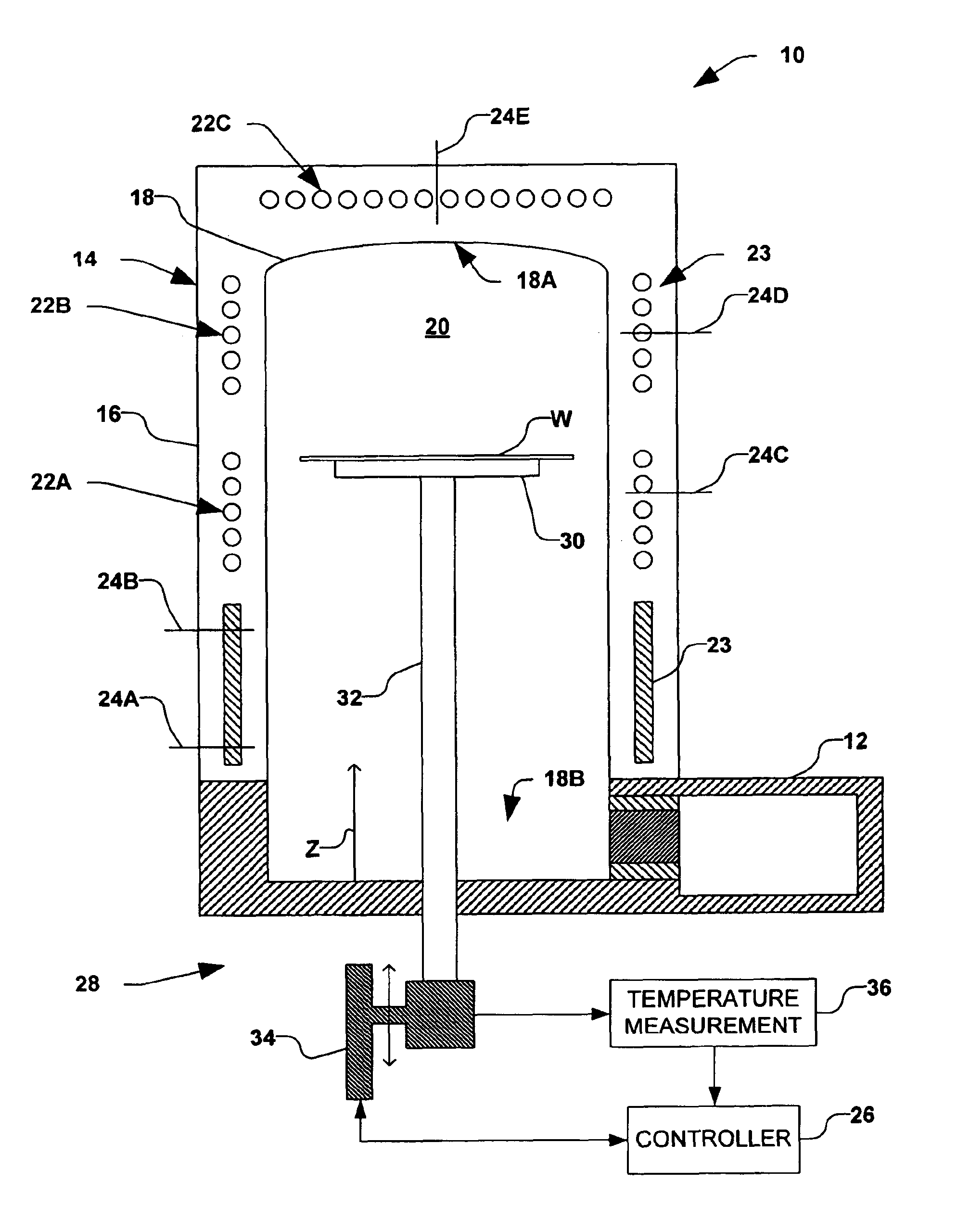
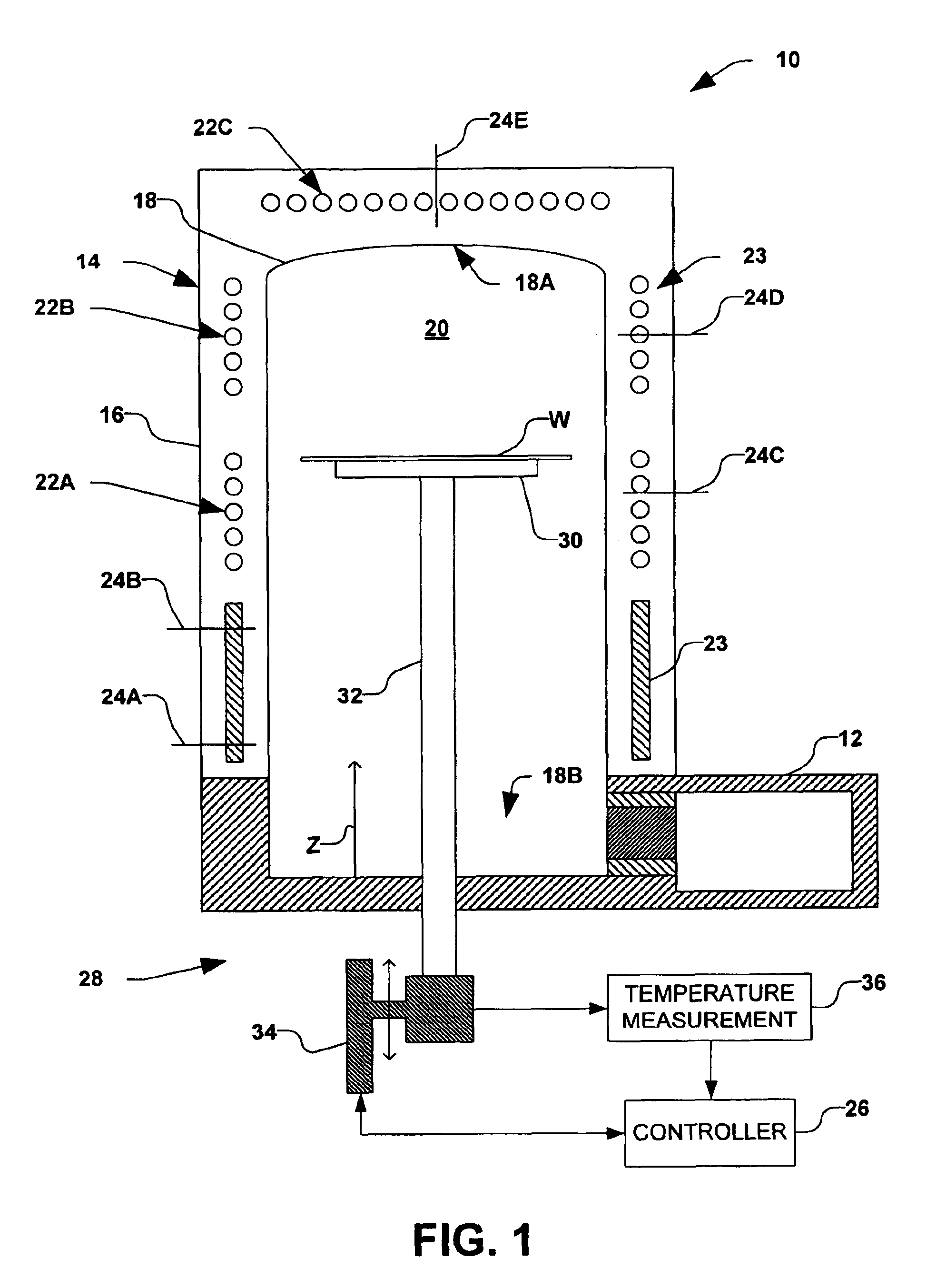
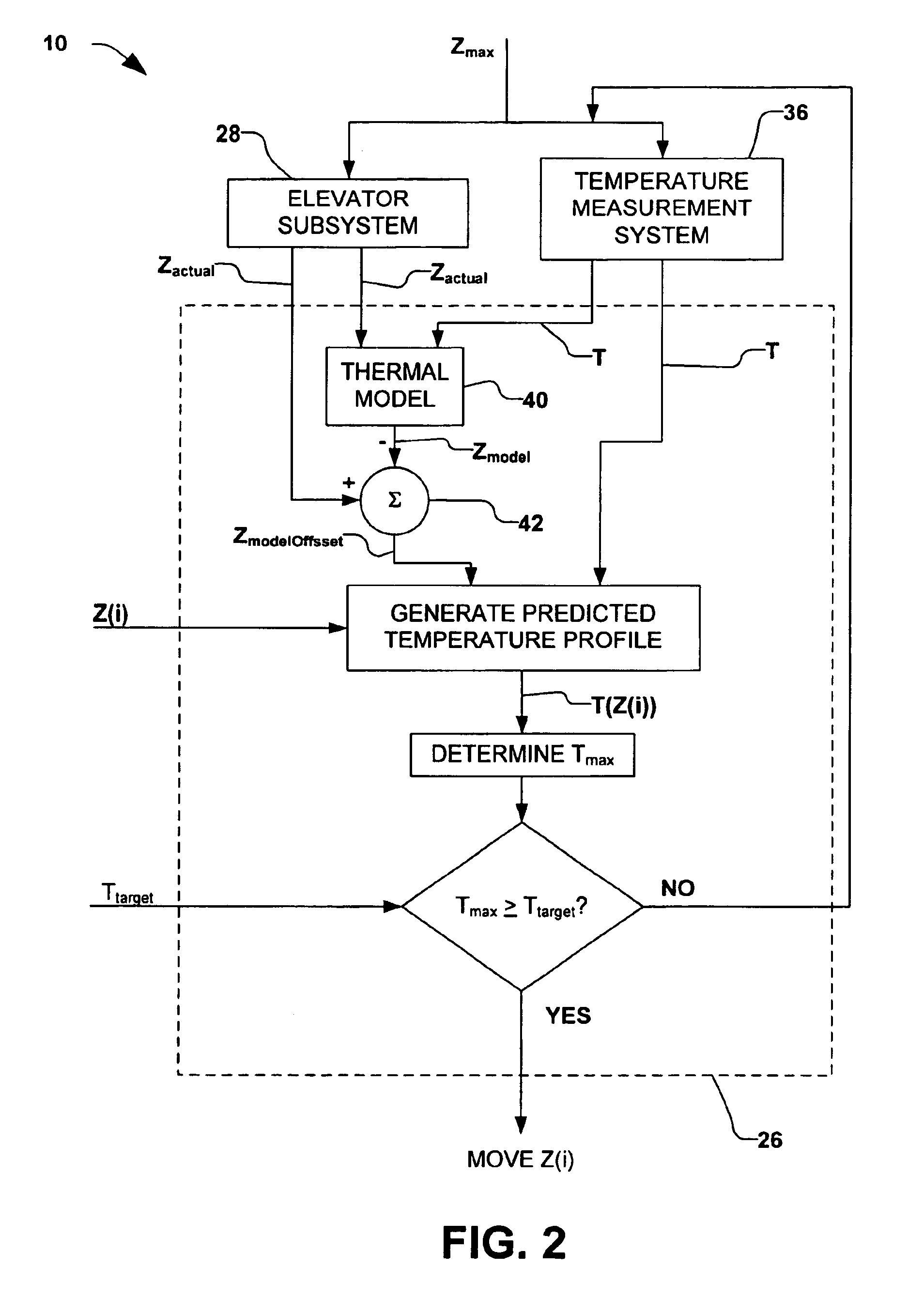
The present invention is generally directed towards a method for thermally processing a substrate. In particular, an amount of heat exposed to the substrate is controlled by predicting a temperature profile of the substrate with respect to time and comparing the prediction to a target value or profile. Accordingly, the present invention will now be described with reference to the drawings, wherein like reference numerals are used to refer to like elements throughout. It should be understood that the description of these aspects are merely illustrative and that they-should not be taken in a limiting sense. In the following description, for purposes of explanation, numerous specific details are set forth in order to provide a thorough understanding of the present invention. It will be evident to one skilled in the art, however, that the present invention may be practiced without these specific details.

In accordance with one aspect of the present invention, a method for thermally proce...


PUM

PropertyMeasurementUnit
temperatureaaaaaaaaaa

Abstract

A method for thermally processing a substrate provides a target substrate temperature and generates a move profile of the substrate within a thermal processing system. An amount of heat is provided to the substrate, and one or more temperatures associated with one or more respective locations on the substrate are measured. A predicted temperature profile is further generated, wherein a predicted temperature of the substrate is based on the amount of heat provided and the one or more measured temperatures. The amount of heat provided to the substrate is further regulated, based on the predicted temperature profile, wherein the substrate is thermally processed generally according to the intended substrate temperature profile. The amount of heat provided to the substrate can be further regulated by controlling a position of the substrate within the thermal processing system.

Description

FIELD OF THE INVENTIONThe present invention relates generally to semiconductor processing systems, and more specifically to a method for controlling a thermal processing of a substrate.BACKGROUND OF THE INVENTIONThermal processing systems have been widely known and used for many years to perform a variety of semiconductor fabrication processes, including annealing, diffusion, oxidation, and chemical vapor deposition. As a result, these processes are well understood, especially with regard to the impact of process variables on the quality and uniformity of resulting products. Thermal processing furnaces typically employ either a horizontal-type furnace or a vertical-type furnace. For some applications, vertical-type furnaces are preferred because they create fewer particles during use, thus decreasing an incidence of contamination and workpiece waste; they can be easily automated, and they typically require less floor space because of their relatively small footprint.Conventional fur...

Claims


Application Information

Patent Timeline
Patent Type & Authority Patents(United States)
IPC IPC(8): H01L21/00F27B17/00F27D19/00
CPCF27B17/0025H01L21/67248H01L21/67109F27D19/00H01L21/324
Inventor MATTHEWS, BRIANWILLIS, JAMES R.LUSTIBER, PAUL E.
Owner AXCELIS TECHNOLOGIES
Why Eureka
Try Eureka