Ultrasound transmitter with voltage-controlled rise/fall time variation

Inactive Publication Date: 2005-02-15
GENERAL ELECTRIC CO
View PDF7 Cites 41 Cited by
  • Summary
  • Abstract
  • Description
  • Claims
  • Application Information

AI Technical Summary

Benefits of technology

The invention provides the following advantages: (1) reducing anomalous variation in rise and fall times without requiring significant increased ASIC die area, which would ordina

Problems solved by technology

This leads to significant variation in the rise time of a high-voltage ultrasound transmitter stage.
This variation can yield distortions in the ultrasound image.
This leads to increased cost due to the need for trimming and larger die area.
In ultrasound imaging, especially when used for

Method used


Image

  • Ultrasound transmitter with voltage-controlled rise/fall time variation
  • Ultrasound transmitter with voltage-controlled rise/fall time variation
  • Ultrasound transmitter with voltage-controlled rise/fall time variation

Examples


Example

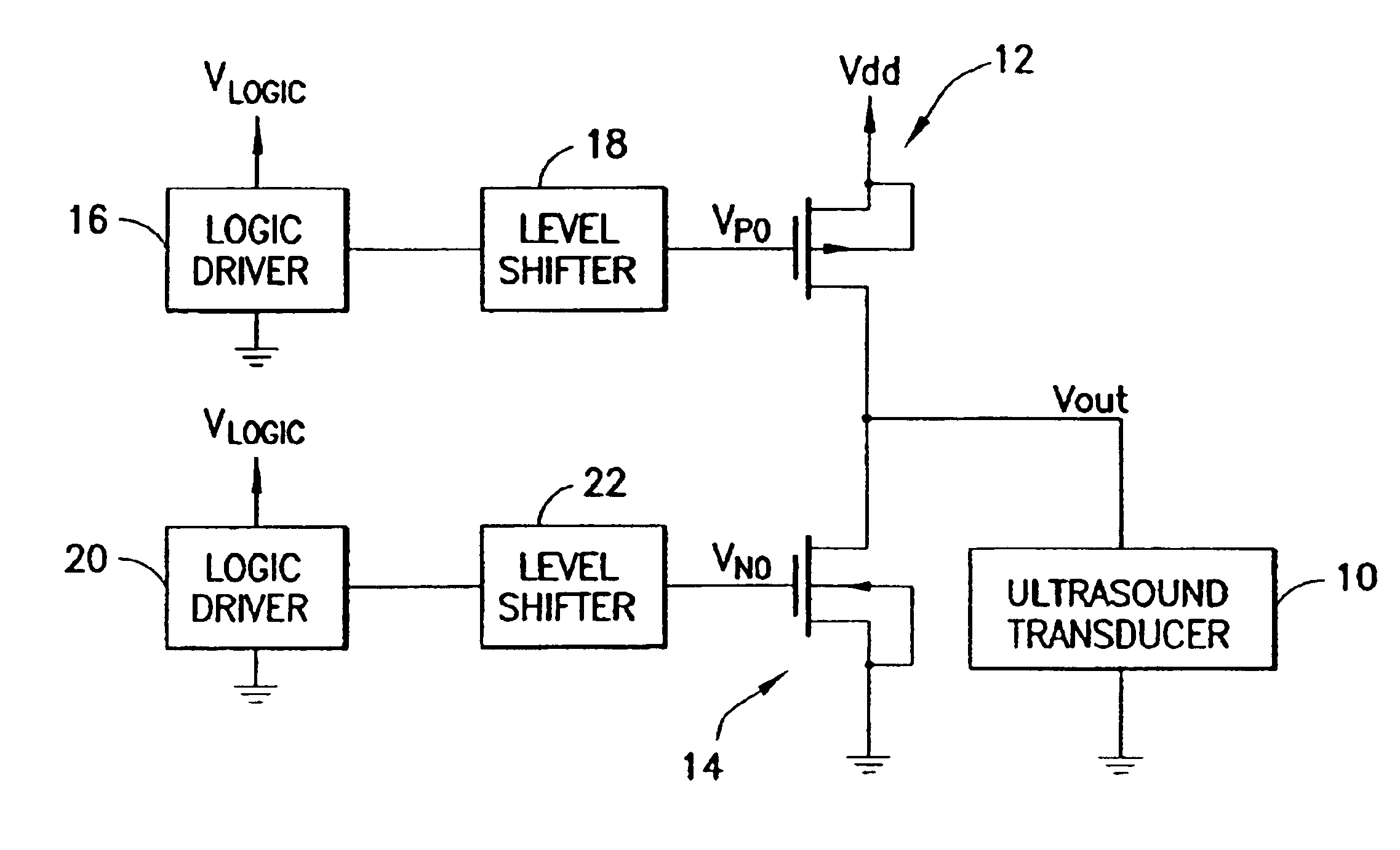
At the outset it should be noted that the connections to ground shown in the drawings are simplifications. In each of the embodiments disclosed herein, the ground terminal is likely to be connected to a negative voltage which is often called Vss. While it is simplest to show this as ground and in some cases (called “unipolar” transmitters) this is in fact the case, the majority of ultrasound machines today use “bipolar” transmitters. In a bipolar transmitter, the source of the NMOS device is connected to a voltage that is usually the negative opposite of the source of the PMOS. So for example, we might have Vdd=+80 V and Vss=−80 V.

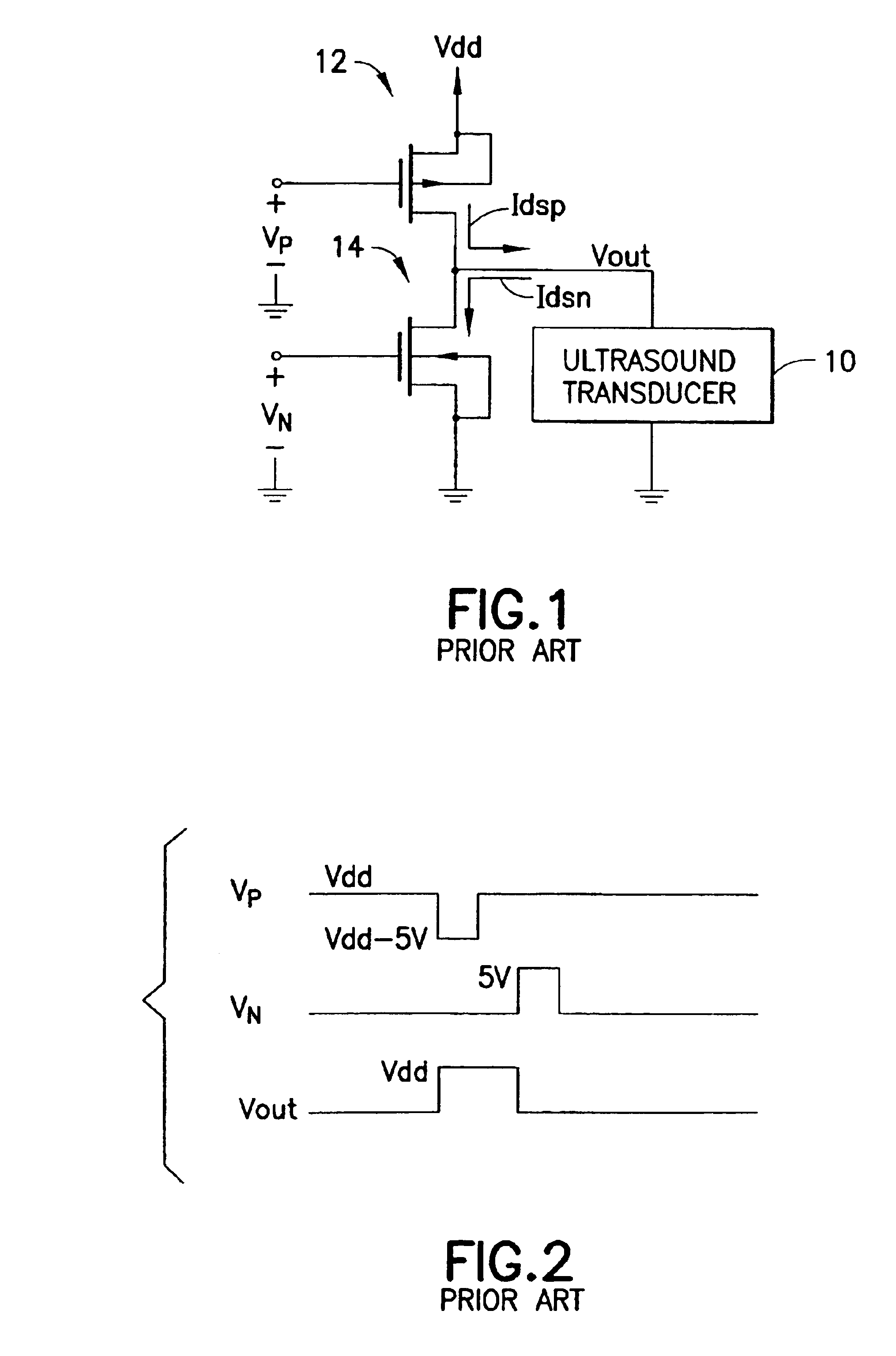
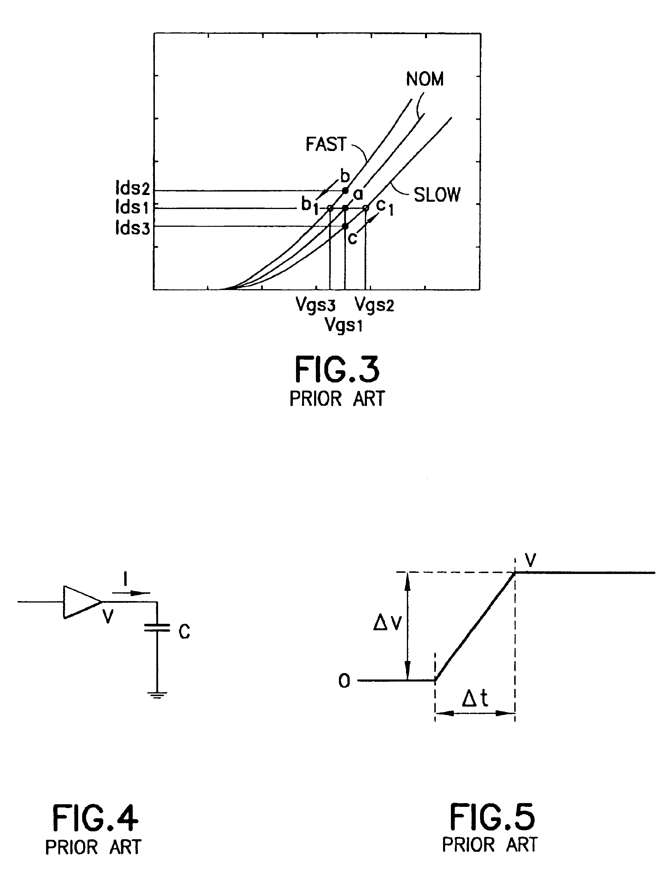
The high-voltage ultrasound transmitter circuit consists of a high-voltage high-current output stage that is controlled by a low-current intermediate stage. The intermediate stage typically drives the gates of the output transistors 5 to 10 V greater (NMOS) or less than (PMOS) the high-voltage supply. The rise time is directly related to the drain-source c...


PUM


Abstract

In an ultrasound transmit ASIC, the rise and fall times of the output pulse can be controlled by varying the gate-source voltage used to drive the output-stage transistors. Control of the rise/fall times can be effected either by trimming on-chip during fabrication or by changing the gate-source voltage that drives the output-stage transistors, either on-chip or off-chip. In all cases it will be necessary to first test the manufactured device to determine how much calibration voltage needs to be applied.

Description

BACKGROUND OF THE INVENTIONThis invention generally relates to integrated circuitry for use in conjunction with ultrasound transducer elements. In particular, the invention relates to ultrasound transmit application-specific integrated circuits (ASICs) for use in ultrasound imaging systems.A medical ultrasound imaging system forms an image by acquiring individual ultrasound lines (or beams). The lines are adjacent to each other and cover the target area to be imaged. Each line is formed by transmitting an ultrasonic pulse in a particular spatial direction and receiving the reflected echoes from that direction. The spatial characteristics of the transmitted wave and the characteristics of the receive sensitivity determine the quality of the ultrasound image. It is desirable that the ultrasound line gathers target information only from the intended direction and ignores targets at other directions.Conventional ultrasound imaging systems comprise an array of ultrasonic transducer eleme...

Claims


Application Information

Patent Timeline
IPC IPC(8): H03K3/00H03K5/12H03K5/01H03K5/156H03K17/16
CPCH03K17/163H03K5/1565
Inventor WODNICKI, ROBERT G.
Owner GENERAL ELECTRIC CO
Why Eureka
Try Eureka