Method and system for calibration of a phase-based sensing system

Active Publication Date: 2005-02-15
MEGGITT SA
View PDF8 Cites 46 Cited by
  • Summary
  • Abstract
  • Description
  • Claims
  • Application Information

AI Technical Summary

Benefits of technology

The present invention provides a calibration technique that enables a sensing system to unambiguously determine the total distance from a transceiver to a target and to track changes in a length of propagation medium between the transceiver and a radiating element (antenna). The calibration technique is applicable to continuous wave, phase-based sensing systems having a transceiver and a radiating eleme

Problems solved by technology

One disadvantage of using this microwave sensing technique is that the propagation medium used to guide the electromagnetic waves to the target contains metal, which can expand and contract in length over changes in temperature.
When the coefficient of thermal expansion (CTE) is large, or a long length of transmission media is used, the change in length of the cable, board, or waveguide over temperature can yield significant errors in the displacement measurement.
In high temperature env

Method used


Image

  • Method and system for calibration of a phase-based sensing system
  • Method and system for calibration of a phase-based sensing system
  • Method and system for calibration of a phase-based sensing system

Examples


Example

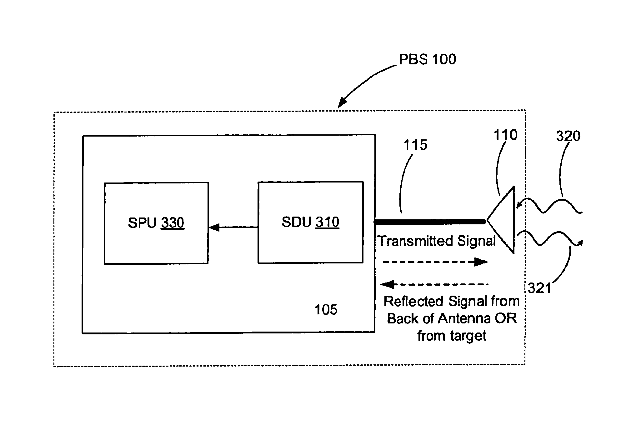
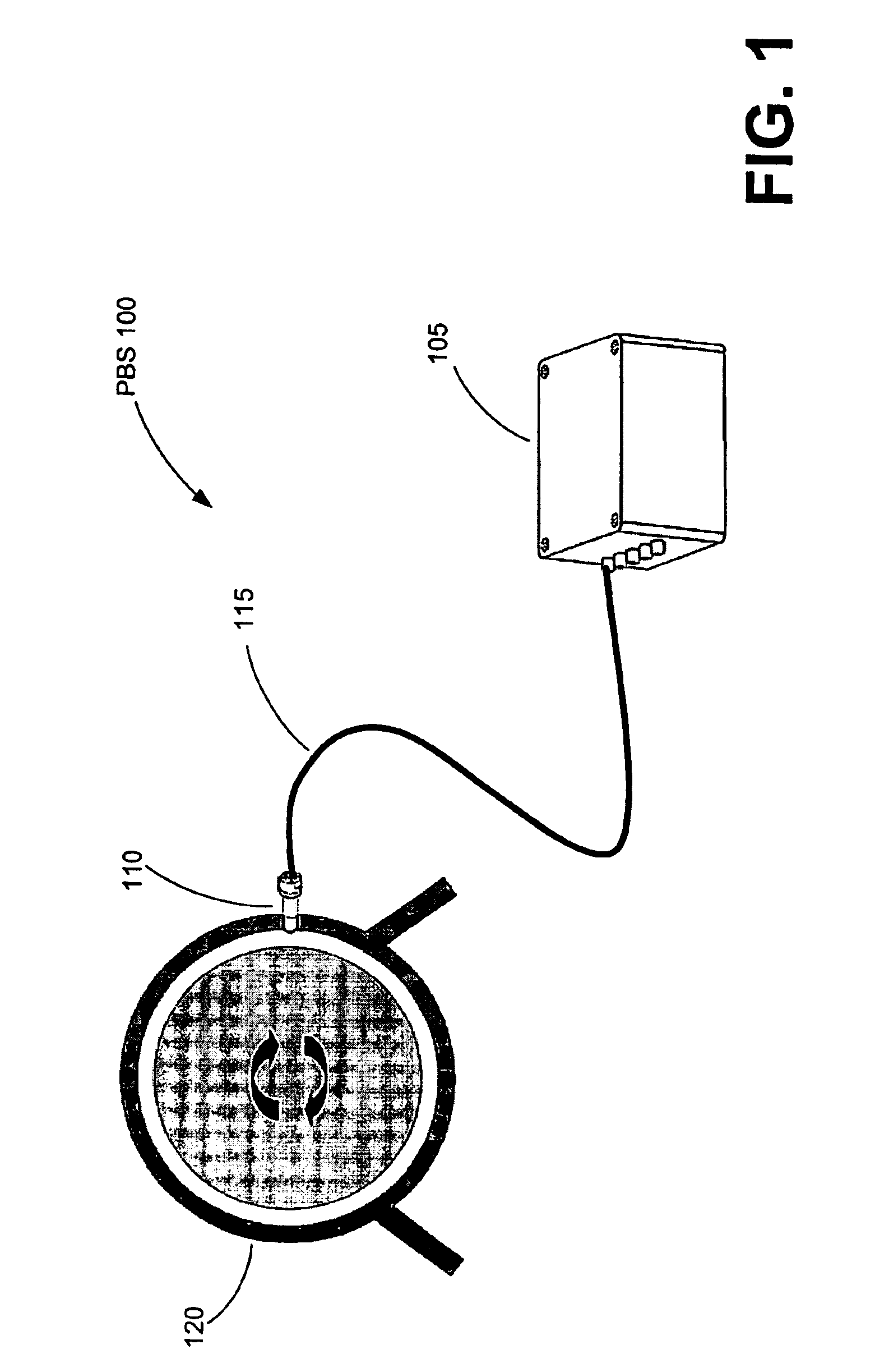
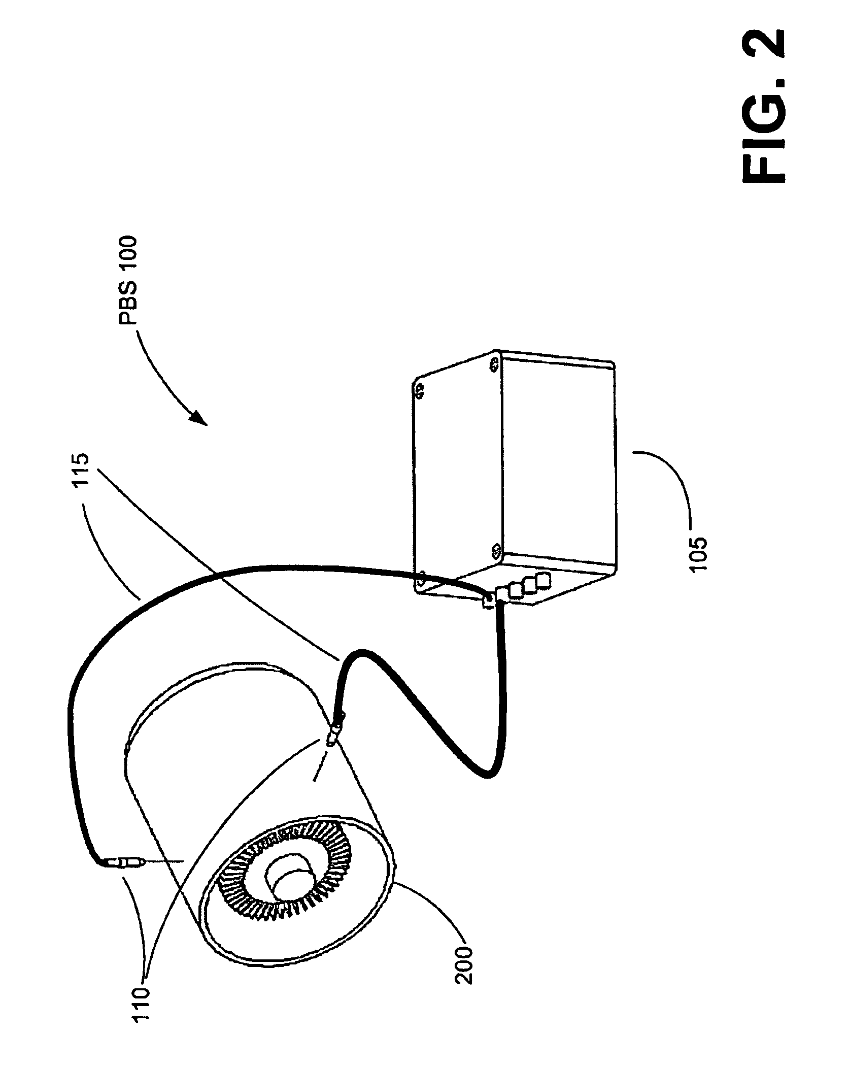
Exemplary embodiments of the present invention provide a calibration technique for a phase-based sensing (PBS) system, or sensing system, such as a phase-based radar system The calibration for the PBS system will now be described more fully hereinafter with reference to FIGS. 1-15, in which embodiments of the invention are shown. FIGS. 1-2 provide illustrations of implementations for an exemplary PBS system with calibration functionality. FIG. 3 provides a block diagram of an exemplary PBS system, with components of the PBS system illustrated in more detail in FIGS. 4, 6 and 7. FIGS. 5A and 5B illustrate a typical antenna / filter reflection coefficient and a representative sweep of the transmit frequency during a calibration task. FIGS. 8, 9, and 10 are representative phasor diagrams used to graphically illustrate the mathematical techniques of the calibration task. FIG. 11 represents how a microwave standing wave can be set-up between the transceiver and the antenna / target for two d...


PUM


Abstract

Calibrating the measurement of a distance between a transceiver and an object such as a radiating element (antenna) or a target by continuously changing the wavelength (frequency) of the transmitted wave and observing the rate of phase shift as a function of change in wavelength. The rate of phase shift change as a function of wavelength can be mathematically related to the total displacement to the reflecting object. This calibration technique is applicable to a sensing device comprising a transceiver configured to transmit a signal toward an object, detectors offset in phase to receive the transmitted signal and a reflected signal, and a processor configured with logic to measure a rate of phase shift proportional to the change in wavelength between the transmitted signal and the reflected signal at the detectors. The processor can be further configured with logic to relate the phase shift to displacement between the transceiver and the reflecting object.

Description

TECHNICAL FIELDThe present invention generally relates to the calibration of sensing systems and, more particularly, to the calibration of non-contact sensing systems, such as phase-based radar systems.BACKGROUND OF THE INVENTIONSensing systems are employed for a wide variety of purposes and in diverse fields. There are sensing systems for detecting motion, surface irregularities, environmental conditions, and for physiological conditions, to name a few. Applications can be used in such industries as medical, process, aeronautical, and others. Such diversity in purpose and industry results in a multitude of considerations for the designer or user of the sensing system. These considerations include cost, precision, linearity, measurement range, durability, maintenance requirements, and even the physical characteristics of the sensed object, among others.Non-contact, or non-invasive, sensing systems are sensing systems that, unlike direct contact sensing systems, do not require the se...

Claims


Application Information

Patent Timeline
IPC IPC(8): G01S13/00G01S13/58G01S7/40G01S13/88
CPCG01S7/4004G01S13/583G01S13/88
Inventor BILLINGTON, SCOTT ALEXANDERGEISHEIMER, JONATHAN LEE
Owner MEGGITT SA
Why Eureka
Try Eureka