Air dryer module

a technology of air dryer and module, which is applied in the direction of colloidal chemistry, braking system, separation process, etc., can solve the problems of limited speed of heavy vehicles and limit the use of heavy vehicles with severely leaking reservoirs, and achieve the effect of reducing potential failure modes and cost effectiv

Inactive Publication Date: 2005-02-22
BENDIX COMML VEHICLE SYST LLC
View PDF51 Cites 23 Cited by
  • Summary
  • Abstract
  • Description
  • Claims
  • Application Information

AI Technical Summary

Benefits of technology

The herein disclosed air brake system's air charging and treatment sub-system referred to as the air dryer reservoir module provides for a simplified and cost effective air charging sub-system, using integrated components. The air dryer reservoir module is configured in a way that allows the elimination of the supply reservoir, which is used in the standard three reservoir system, while providing a means of simultaneously sensing both the primary reservoir and the secondary reservoir for air compressor and air dryer control.
The air dryer reservoir module integrates components such as pressure protection valves, the air compressor governor, pressure relief valves pressure sensors and the like in a way that eliminates the need for the supply reservoir, the supply reservoir safety valve, several of the standard three reservoir system's external lines and many of its fittings. The reduction of components, fittings and pneumatic lines reduces potential failure modes. With respect to a standard three, reservoir system, the air dryer reservoir module integrates the following components: air dryer, primary and secondary check valves, supply and secondary drain valves, supply reservoir safety valve, the compressor governor, auxiliary system pressure protection valves, and the supply and secondary reservoirs.

Problems solved by technology

A failure detection means is also disposed within the housing for detecting a failure of the pneumatic circuits which are fed by the primary and secondary reservoirs and in the event of a failure of these pneumatic circuits the speed of the heavy vehicle is limited.
Thereby limiting the use of the vehicle with a severely leaking reservoir.

Method used


Image

  • Air dryer module
  • Air dryer module
  • Air dryer module

Examples


Embodiment Construction

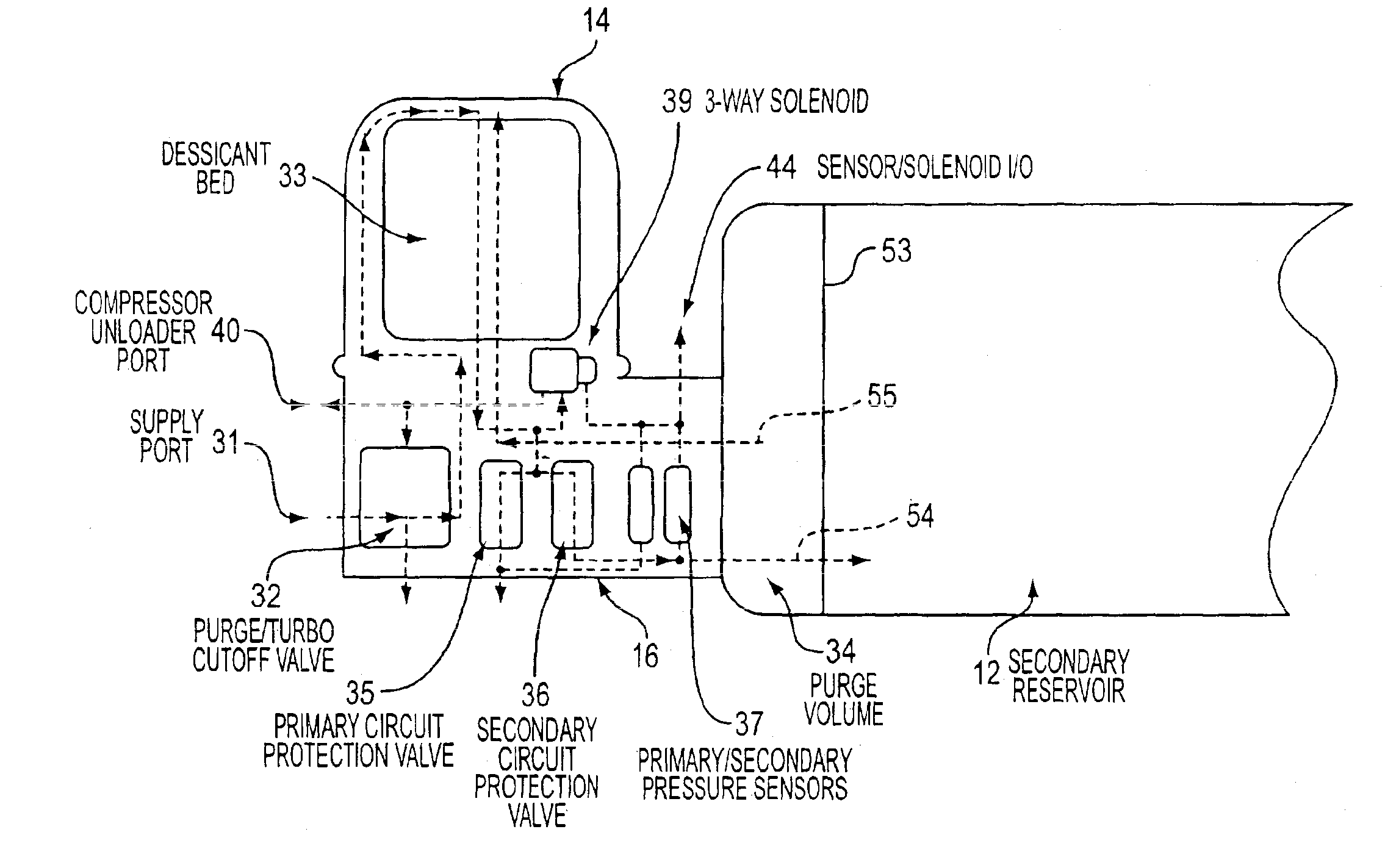
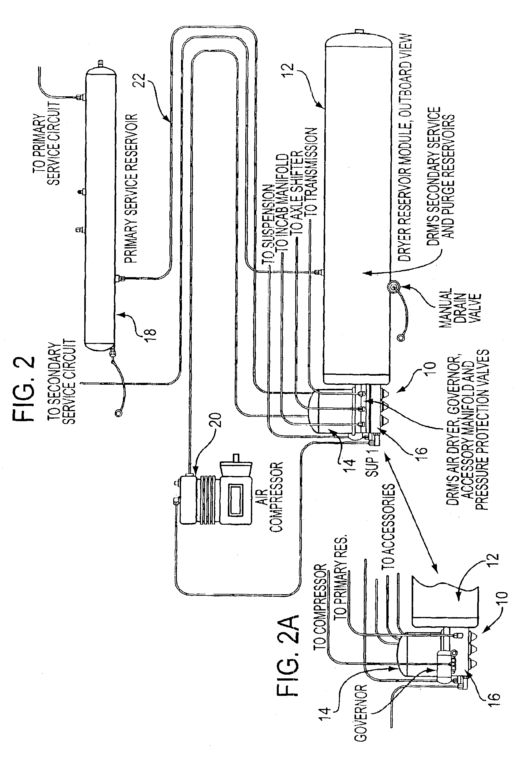
Referring now to the drawings and FIGS. 2 and 3 in particular there is shown an air dryer reservoir module 10 according to the present invention. The air dryer module 10 provides compressed air received from an air compressor 20 for operating the braces of a heavy motor vehicle. The air dryer module 10 includes an air dryer 14 connected to receive compressed air from the air compressor 20, a secondary air reservoir 12 separate from the air dryer 14, and a housing 16 containing pneumatic circuit components for controlling the flow of compressed air from the air compressor 20 through the air dryer 14 to the secondary reservoir 12 and a primary reservoir 18. The housing 16 has the air dryer 14 securely attached to one section thereof and the secondary reservoir 12 securely attached to another section thereof for joining the air dryer 14 and the secondary reservoir 12 together forming the unitary air dryer reservoir module 10. The compressed air brake system with the air dryer reservoir...


PUM


Abstract

An air dryer and reservoir assembly for providing compressed air from an air compressor (20) on a heavy motor vehicle which includes an air dryer (14) connected to receive compressed air from the air compressor (20) and a secondary reservoir (12), including an integral purge volume (34), for storing compressed air which passes through the air dryer (14), with the air dryer (14) and the secondary reservoir (12) being securely attached to a housing (16) to form an air dryer reservoir module (10). A primary, reservoir (18) for storing compressed air from the air dryer (14) is located remote from the air dryer reservoir module (10). A pressure equalizing mechanism (57) is disposed between the primary reservoir (18) and the secondary reservoir (12) for keeping pressure in the two reservoirs (12,18) equal. Components located within the housing (16) control air flow between the air dryer (14) and the primary and secondary reservoirs (18,12) and also monitor the pneumatic brake system circuits fed by the primary and secondary reservoirs (18,12).

Description

BACKGROUND OF THE INVENTION1. Field of the InventionThis invention relates to air dryers and more particularly to an air dryer and a reservoir, including a separate purge volume, constructed together as a module,2. Description of Prior ArtAir dryers have been used to dry the air in a heavy vehicle air, brake system for many years. The advantages of clean and dry air in air brake systems has long been recognized, as moisture entrained in the air brake system may during cold weather operation cause the components of the air brake system to freeze, thus rendering the system inoperable. These prior art air dryers normally include a desiccant material through which the compressed air flows. When the vehicle air compressor has charged the vehicle air reservoirs to a sufficient pressure level, the compressor is unloaded so that the compressor no longer compresses air. When the compressor is unloaded, a signal is transmitted to a purge valve carried within the air dryer which causes stored ...

Claims


Application Information

Patent Timeline
Patent Type & Authority Patents(United States)
IPC IPC(8): B01D53/26B01D53/04B60T17/06B60T17/00F15B1/00F15B1/26F15B21/00F15B21/04F15B21/048
CPCB01D53/0415B01D53/261B60T17/004B60T17/06F15B1/26F15B21/048Y10S55/17B01D53/053B01D2257/80B01D2259/40003B01D2259/40009B01D2259/40081B01D2259/40086B01D2259/4566B01D53/0454
Inventor QUINN, LEONARD A.HOFFMAN, FRED W.GOODELL, DAVID J.
Owner BENDIX COMML VEHICLE SYST LLC
Why Eureka
Try Eureka