Electrodeless excimer UV lamp

Inactive Publication Date: 2005-02-22
OLD DOMINION UNIVERSITY RESEARCH FOUNDATION
View PDF9 Cites 25 Cited by
  • Summary
  • Abstract
  • Description
  • Claims
  • Application Information

AI Technical Summary

Benefits of technology

Unfortunately, known excimer lamps employ a geometry that renders them relatively inefficient. For example, known excimer lamps include a perforated metal or a mesh-like metallic outer electrode with a cylindrical geometry that blocks a substantial portion of the emitted UV radiation and therefore prevents a substantial portion of the emitted UV radiation from propagating outside the lamp. For most applications, such as, for example, the decontamination of a liquid, it is advantageous to maximize the UV emitting area.
Using the electrodeless excimer UV lamp of this invention, generation of a near monochromatic UV radiation is achieved, using, for example, a gas mixture containing krypton and chlorine as the operating gas mixture. For example, UV excimer radiation with a wavelength of 222 run has a very powerful germicidal effect and can be useful in liquid purification.
Additionally, by placing the electrodes around the outer surface of the chamber, the electrodes do not come into contact with the discharge, but are sufficiently separated from the plasma constituents to prevent interaction with the electrode material. Therefore, no contamination of the discharge by the electrodes occurs. Furthermore, the electrodes are capacitively coupled to the plasma discharge, such that the electrodes do not function as a conductor and the electrodeless excimer UV lamp does not overheat. Therefore, a cooling system is typically not required for efficient operation of the electrodeless excimer UV lamp.
In various exemplary embodiments, the electrodeless excimer UV lamp includes several electrodes placed around the outer surface of the chamber in a cascaded fashion. By cascading several electrodes around the chamber, a larger discharge volume may be created within the chamber, and a larger UV emission area can be created. This ultimately increases the UV output of the excimer UV lamp.

Problems solved by technology

Unfortunately, known excimer lamps employ a geometry that renders them relatively inefficient.
During operation of known excimer lamps the plasma discharge reacts with the electrodes and, while pitting or etching the electrode material, contaminates the discharge with impurities.
Electrode contamination has a negative effect on UV generation, and limits the lamp lifetime.

Method used


Image

  • Electrodeless excimer UV lamp
  • Electrodeless excimer UV lamp
  • Electrodeless excimer UV lamp

Examples


Embodiment Construction

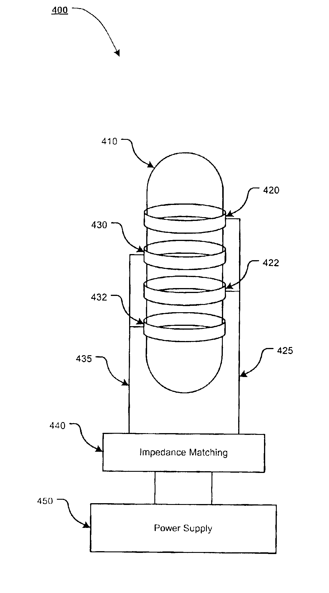
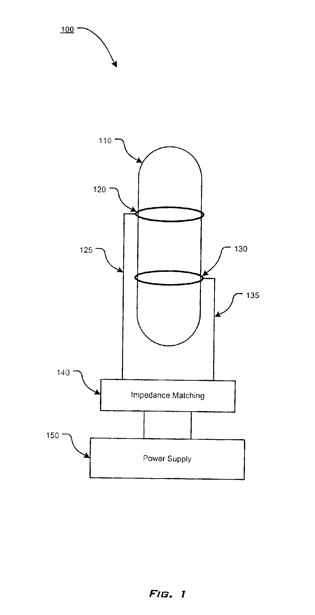
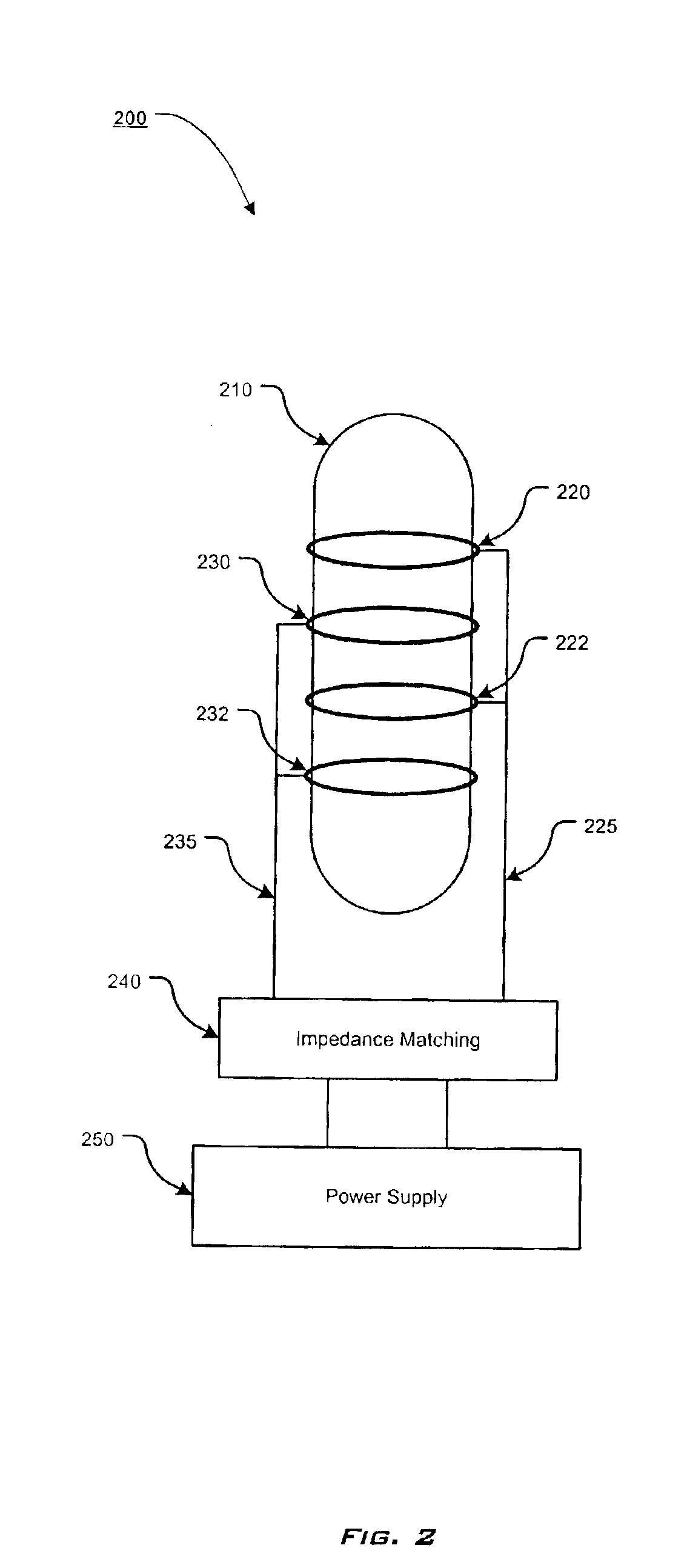
For simplicity and clarification, the layout, design factors, and operating principles of the apparatuses, systems, and methods of the electrodeless excimer UV lamp according to this invention are explained with reference to various exemplary embodiments of the apparatuses, systems, and methods of the electrodeless excimer UV lamp according to this invention. The basic explanation of the operation of the apparatuses, systems, and methods of the electrodeless excimer UV lamp is applicable for the understanding and design of the constituent components employed in the apparatuses, systems, and methods of the electrodeless excimer UV lamp of this invention.

It should be understood that the term “high pressure”, as used herein, refers to pressures from a few torr to approximately a thousand torr.

It should also be understood that the term “electrodeless”, as used herein, are to be understood to reflect the idea that a plasma discharge is generated within an enclosed chamber. Thus, an elect...


PUM

PropertyMeasurementUnit
Electric potential / voltageaaaaaaaaaa
Widthaaaaaaaaaa

Abstract

An electrodeless excimer UV lamp, comprising an enclosed chamber with a gas sealed within the enclosed chamber, wherein the gas is capable of being used to generate a plasma discharge, a first electrode wrapped around the outer surface of the chamber at a first location, a second electrode wrapped around the outer surface of the chamber at second location, and a power supply configured to apply a voltage to the first electrode and the second electrode. During operation of the UV lamp, a plasma discharge is generated by applying a voltage to the electrodes wrapped around the outer surface of the chamber to ignite the gas or gas mixture inside the chamber and generate a plasma discharge within the chamber, such that a specific wavelength of UV radiation will be generated by the particular gas within the chamber.

Description

BACKGROUND OF THE INVENTION1. Field of the InventionThis invention relates to excimer UV lamps.2. Description of Related ArtGenerally, it is known that excimers (excited dimers) are excited molecules with no stable ground state. They are formed via three body reactions involving excited-state atoms and ground state atoms. Excimers are normally unstable and decay in few nanoseconds, yielding incoherent radiation in the ultra-violet (UV) and vacuum ultra-violet (VUV) range. Excimers can be formed in high pressure, non-equilibrium, gas discharges such as the Dielectric Barrier Discharge (DBD).Excimer formation typically occurs at high pressures where the collision rates are high. Therefore, a non-equilibrium, atmospheric pressure discharge provides an ideal source of excimers. In the market today, excimer UV lamps have generally a cylindrical configuration and are based on a silent discharge. This silent discharge is normally generated by applying an AC voltage to electrodes, which are...

Claims


Application Information

Patent Timeline
IPC IPC(8): H01J65/00H01J7/00H01J7/24H01J65/04
CPCH01J65/046
Inventor LAROUSSI, MOUNIR
Owner OLD DOMINION UNIVERSITY RESEARCH FOUNDATION
Why Eureka
Try Eureka