Data transfer scheme in a communications system incorporating multiple processing elements

a communication system and data transfer technology, applied in the field of embedded systems, can solve the problems of increasing system cost, complex circuitry of processing elements in embedded systems, and complicated system control, and achieve the effect of efficient data transfer

Inactive Publication Date: 2005-02-22
COMSYS COMM & SIGNAL PROC
View PDF23 Cites 72 Cited by
  • Summary
  • Abstract
  • Description
  • Claims
  • Application Information

AI Technical Summary

Benefits of technology

The present invention is a data transfer scheme for efficiently transferring data between a processing element comprising multiple data generating processing units and a processor comprising a demultiplexer that overcomes the disadvantages and problems associated with prior art data transfer schemes. The scheme is beneficial in any application where a communications bridge is required between multiple data sources and one or more sinks of unmatched numbers, i.e. several data sources communicating with one or more data sinks. The scheme is especially applicable for use in systems that require multiplexed data derived from a plurality of data generating sources to be transferred to several processing entities.

Problems solved by technology

Often times, however, processing elements in the embedded system comprise complex circuitry and are adapted to generate multiple output data streams from several data generating units within the system.
Such an interface typically requires multiple instances of the techniques described above, e.g., multiple DMA controllers or multi-channel DMA controllers, multiple shared memories, multiple FIFOs, etc., which requires more complicated system control and increases the system cost.
A disadvantage of this prior art data transfer scheme is that it is costly due to the requirement of providing multiple buffers in the shared memory along with bus arbitration logic circuitry.
In addition, in the case of cyclic buffers, the system control required for the proper operation of the embedded system is complicated since each buffer requires separate control circuitry for maintaining read and write pointers, etc.
In the case where the number of active hardware units and the data output rate of each unit is configurable each cycle, additional control circuitry is required increasing the system control complexity even further.

Method used


Image

  • Data transfer scheme in a communications system incorporating multiple processing elements
  • Data transfer scheme in a communications system incorporating multiple processing elements
  • Data transfer scheme in a communications system incorporating multiple processing elements

Examples


Embodiment Construction

Notation Used Throughout

The following notation is used throughout this document.

TermDefinitionASICApplication Specific Integrated CircuitBPFBand Pass FilterCDMACode Division Multiple AccessCPICHCommon Pilot ChannelCPUCentral Processing UnitDMADirect Memory AccessDSPDigital Signal ProcessorFIFOFirst In First OutFPGAField Programmable Gate ArrayIFIntermediate FrequencyIRQInterrupt RequestMRCMaximal Ratio CombiningPDAPersonal Digital AssistantRAMRandom Access MemoryRFRadio FrequencyRSSIReceived Signal Strength IndicationUEUser EquipmentUMTSUniversal Mobile Terrestrial ServiceW-CDMAWideband Code Division Multiple Access

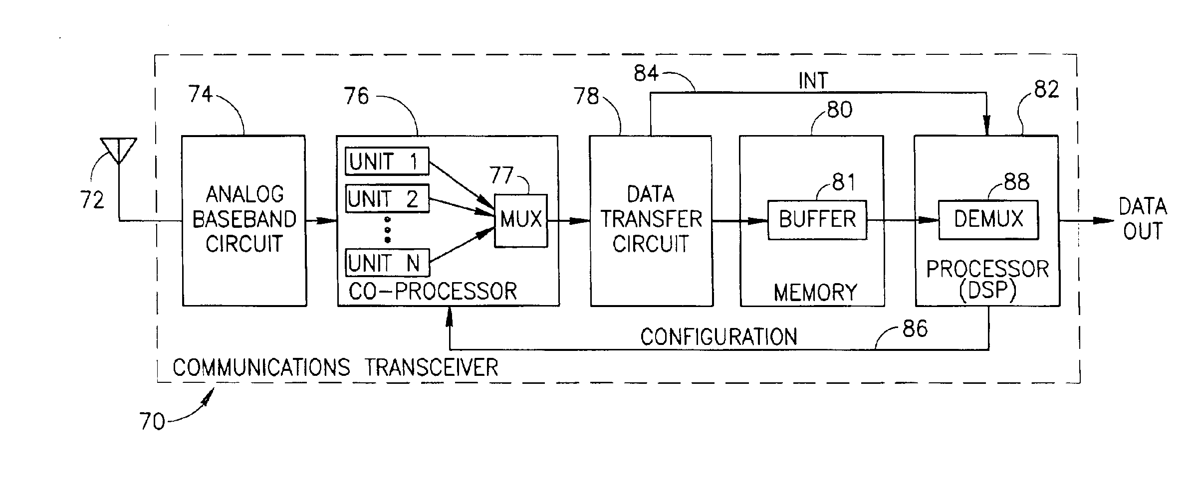
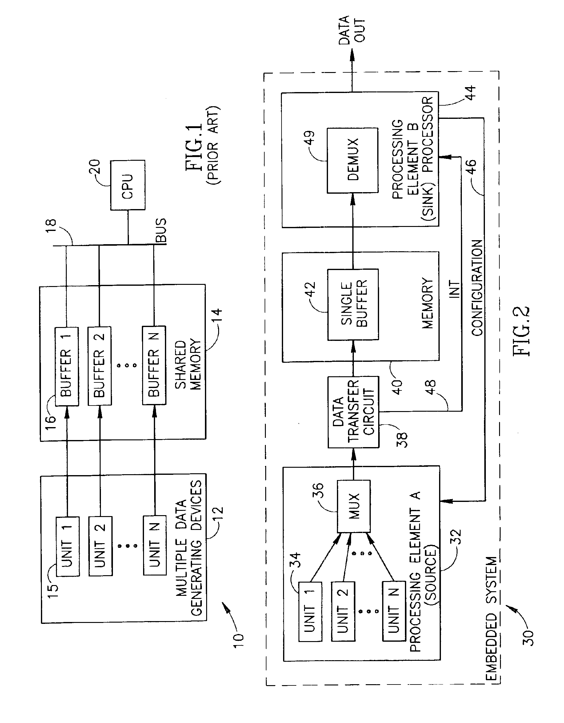
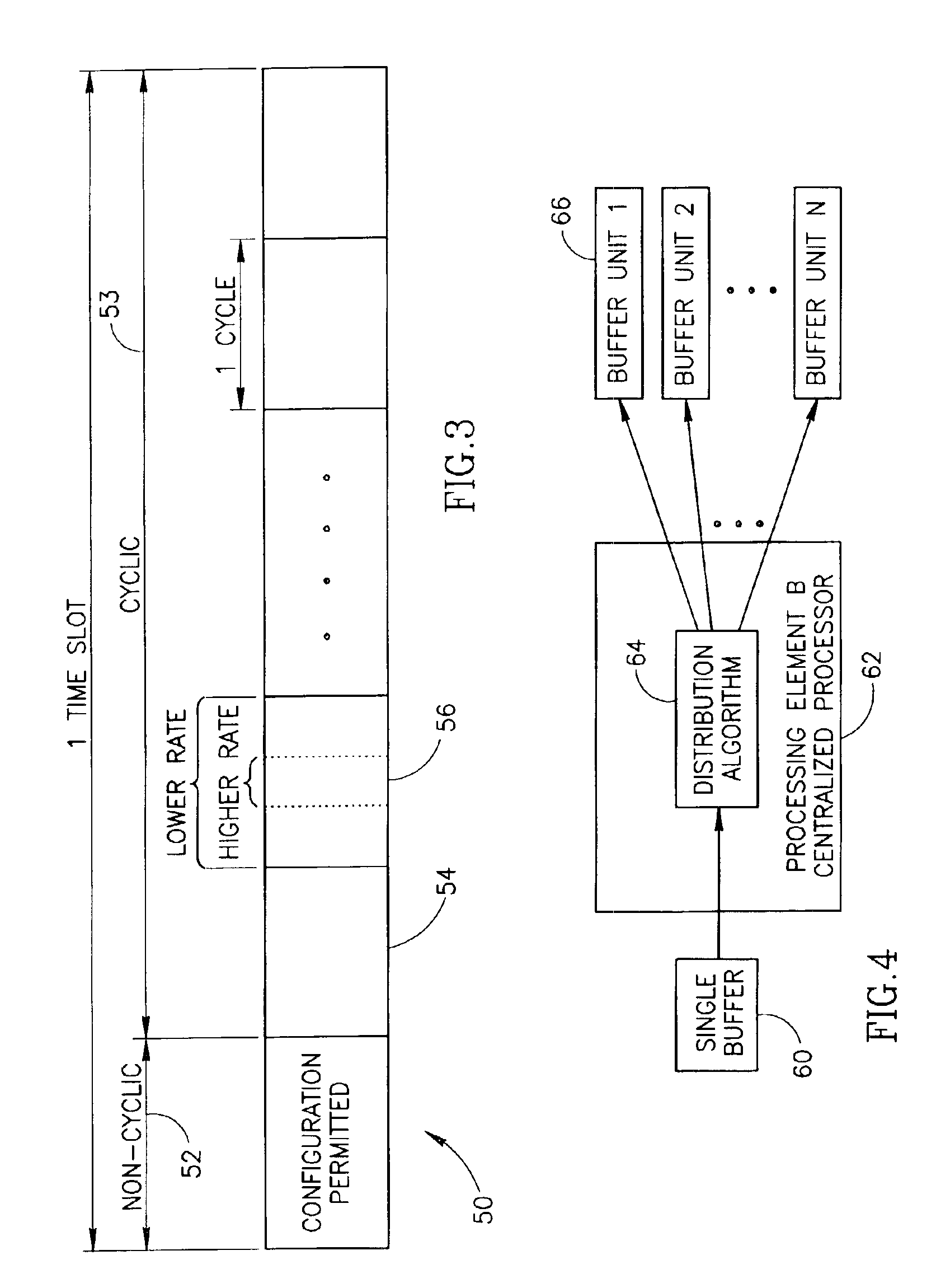
The present invention is a data transfer scheme for efficiently transferring data between multiple data generating processing units in a processing element and a sink processor comprising a demultiplexing processor that overcomes the disadvantages and problems associated with prior art data transfer schemes. The scheme is beneficial in any application where a communicatio...


PUM


Abstract

A novel data transfer scheme for efficiently transferring data between multiple data generating processing units in a processing element wherein each processing unit may generate data at different rates. The data output of each processing unit is multiplexed into a single data stream and written to a memory buffer. A centralized software processor such as a CPU or DSP implements a demultiplexer operative to read the contents of the input buffer, demultiplex the data and distribute it to individual unit buffers thus recreating the original data streams generating by each of the processing units. The multiplexed data stream is generated by partitioning the outputs of the data generating processing units into multiple multiplexer groups based on individual data rates. The outputs of the various groups are collected by a multiplexer and used to build a single data stream having a well-defined structure.

Description

FIELD OF THE INVENTIONThe present invention relates generally to the area of embedded systems and more particularly relates to an efficient data transfer scheme for transferring data between multiple processing elements via a centralized distribution entity.BACKGROUND OF THE INVENTIONMany systems, especially communication systems, are constructed from a plurality of processing elements that must communicate with each other for proper operation of the system. Different processing elements may include any type of hardware circuit element, software processing device, hardware accelerator module, central processing unit (CPU), etc. For example, data output from several processing units may need to be multiplexed and communicated to different processing elements for further processing. Numerous techniques and methods for transferring data between processing elements are known in the art. Several techniques for enabling communication between two processing elements include bidirectional b...

Claims


Application Information

Patent Timeline
Patent Type & Authority Patents(United States)
IPC IPC(8): H04J1/16H04B7/204H04J1/00H04B7/216H04L12/28
CPCH04J3/1682G06F13/1663
Inventor SEGAL, ORENAVITAL, YANIVMOSHE, MOSHERESHEF, EHUD
Owner COMSYS COMM & SIGNAL PROC
Why Eureka
Try Eureka