Method and apparatus for monitoring catalyst requirements of a fluid catalytic cracking catalyst injection system

a technology of fluid catalytic cracking and injection system, which is applied in the direction of liquid/fluent solid measurement, error detection/correction, instruments, etc., can solve the problems of requiring a plurality of bolts to remove, servicing or obtaining items within the housing, and requiring time-consuming and labor-intensive processes

Inactive Publication Date: 2005-02-22
JOHNSON MATTHEY PROCESS TECH
View PDF14 Cites 72 Cited by
  • Summary
  • Abstract
  • Description
  • Claims
  • Application Information

AI Technical Summary

Benefits of technology

A method and apparatus for monitoring catalyst requirements of a fluid catalytic cracking catalyst injection system is provided. In one embodiment, a method for monitoring catalyst requirements of a fluid catalytic cracking catalyst injection system includes the steps of communicating with a memory device of a control module of the catalyst inje...

Problems solved by technology

Thus, access to the contents of the enclosure, e.g., a controller, requires a time-consuming process of removing a plurality of bolts.
Moreover, as the controller is now exposed to the potentially hazardous environment, high-level authorization from plant operations management is typically required as certain processing activities must be stopped to minimize the presence of hazardous gases.
Thus, servicing or obtaining items within the housing, such as a disk containing historical information regarding catalyst injection events from the controller, is both difficult and time consuming, and may require an interruption in processing activities.
Moreover, as catalyst usage information is retrieved only periodically from the injection system, the amount of catalyst inventoried (i.e., catalyst warehoused and queued in the injection system) at a facility is often difficult to determine.
Particularly as catalyst injection may be unscheduled (i.e., not part of production planning) due to instantaneous needs or to correct process trends, the rate of catalyst usage may vary while the amount of catalyst stored in the injection system may not be known until downloading that information from the i...

Method used


Image

  • Method and apparatus for monitoring catalyst requirements of a fluid catalytic cracking catalyst injection system
  • Method and apparatus for monitoring catalyst requirements of a fluid catalytic cracking catalyst injection system
  • Method and apparatus for monitoring catalyst requirements of a fluid catalytic cracking catalyst injection system

Examples


Embodiment Construction

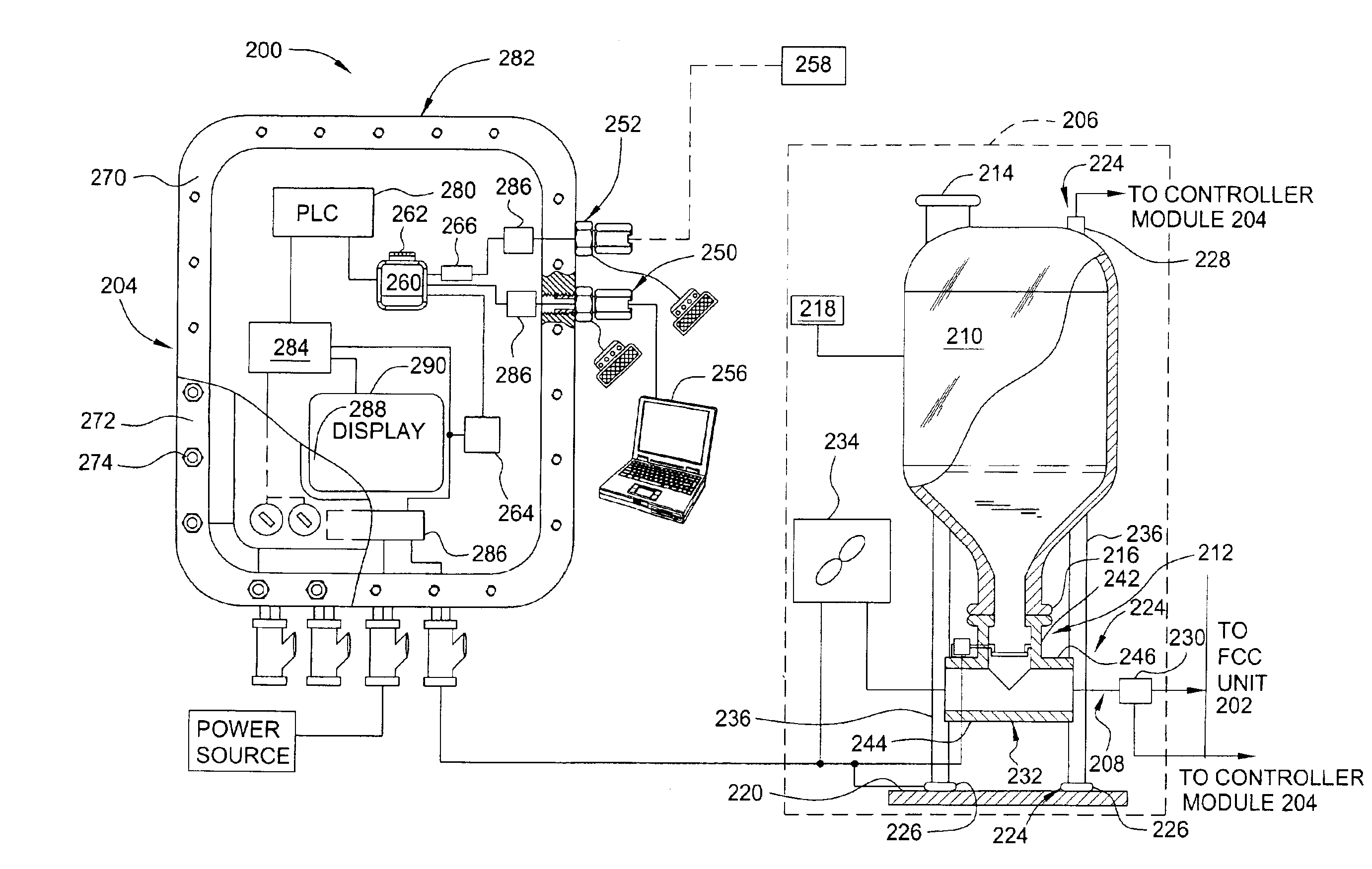
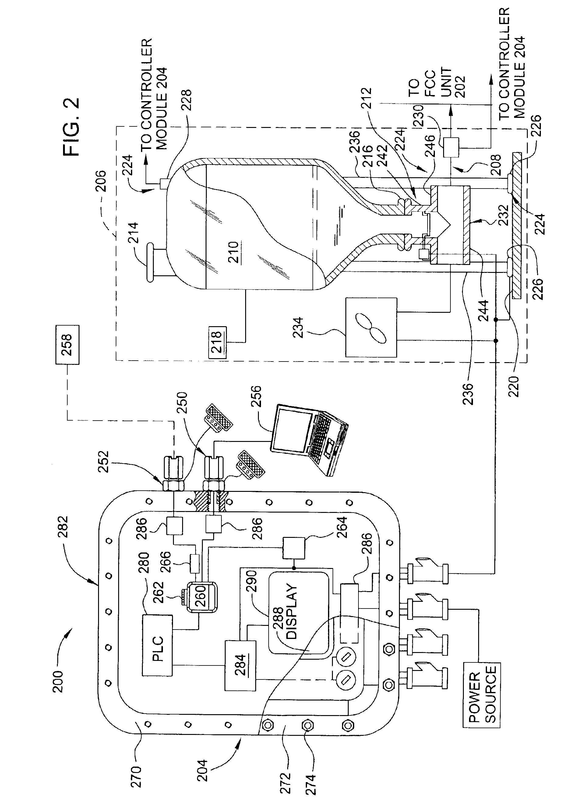
FIG. 2 depicts one embodiment of a fluid catalytic cracking (FCC) system 200 comprises a control module 204 and an injection system 206, where the control module 206 is configured to facilitate local data access of information obtained from the injection system 206. The FCC system 200 also includes a fluid catalytic cracking (FCC) unit 202 coupled to a catalyst injection system 206. The FCC unit 202 is adapted to promote catalytic cracking of petroleum feed stock and may be configured in a conventional manner. The injection system 206 is coupled to the FCC unit 202 and is configured to inject one or more catalysts into the FCC unit 202 to control processing attributes such as the ratio of products recovered in a distiller of the FCC unit 202 and / or to control the emissions from the FCC unit 202. The control module 204 is coupled to the injection system 206 to control the rates and / or amounts of catalyst provided to the FCC unit 202 by the injection system 206.

In one embodiment, the ...


PUM


Abstract

A method and apparatus for monitoring catalyst requirements of a fluid catalytic cracking catalyst injection system is provided. In one embodiment, a method for monitoring catalyst requirements of a fluid catalytic cracking catalyst injection system includes the steps of communicating with a memory device of a control module of the catalyst injection system that is adapted to control the amount of catalyst injected into a fluid catalyst cracking unit and determining if catalyst inventory needs to be replenished. The method enables both suppliers and processors to remotely monitor inventory requirements and take appropriate action if inventories fall below a predefined level or reorder point.

Description

BACKGROUND OF THE INVENTION1. Field of the InventionEmbodiments of the invention generally relate to a method and apparatus for monitoring catalyst requirements of a fluid catalytic cracking catalyst injection system, and the like.2. Description of the Related ArtFIG. 1 is a simplified schematic of a conventional fluid catalytic cracking system 130. The fluid catalytic cracking system 130 generally includes a fluid catalytic cracking (FCC) unit 110 coupled to a catalyst injection system 100, an oil feed stock source 104, an exhaust system 114 and a distillation system 116. One or more catalysts from the catalyst injection system 100 and oil from the oil feed stock source 104 are delivered to the FCC unit 110. The oil and catalysts are combined to produce an oil vapor that is collected and separated into various petrochemical products in the distillation system 116. The exhaust system 114 is coupled to the FCC unit 110 and is adapted to control and / or monitor the exhausted byproducts...

Claims


Application Information

Patent Timeline
IPC IPC(8): C10G11/18C10G11/00
CPCB01J8/0015B01J8/003B01J8/0035C10G11/187C10G11/18B01J2208/00761B01J2208/00769B01J2208/00752
Inventor EVANS, MARTIN
Owner JOHNSON MATTHEY PROCESS TECH
Why Eureka
Try Eureka