
Exhaust gas purification system for internal combustion engine

Inactive Publication Date: 2005-03-01
TOYOTA JIDOSHA KK
View PDF13 Cites 18 Cited by
  • Summary
  • Abstract
  • Description
  • Claims
  • Application Information

AI Technical Summary

Benefits of technology

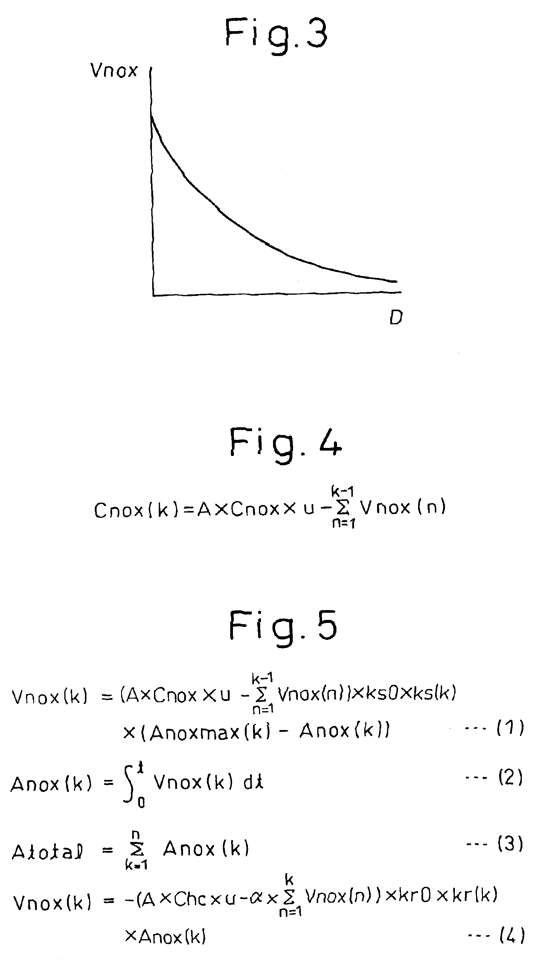
[0021]According to the eleventh invention, in the eighth invention, the component includes NOx absorbed into the NOx catalyst when the rich spike operation is not executed and the reducing component for reducing the NOx absorbed into the NOx catalyst when the rich spike operation is executed, and the total component amount calculated by the second calculation means is a value obtained by accumulating the amount of NOx absorbed into the NOx catalyst when

Problems solved by technology

Then, NOx can no longer be absorbed into the NOx catalyst and flows out downstream from the NOx catalyst, thereby deteriorating the emission.
With the means mentioned above, therefore, the total absorbed NOx amount cannot always be detected accurately.

Method used


Image

  • Exhaust gas purification system for internal combustion engine
  • Exhaust gas purification system for internal combustion engine
  • Exhaust gas purification system for internal combustion engine

Examples


second embodiment

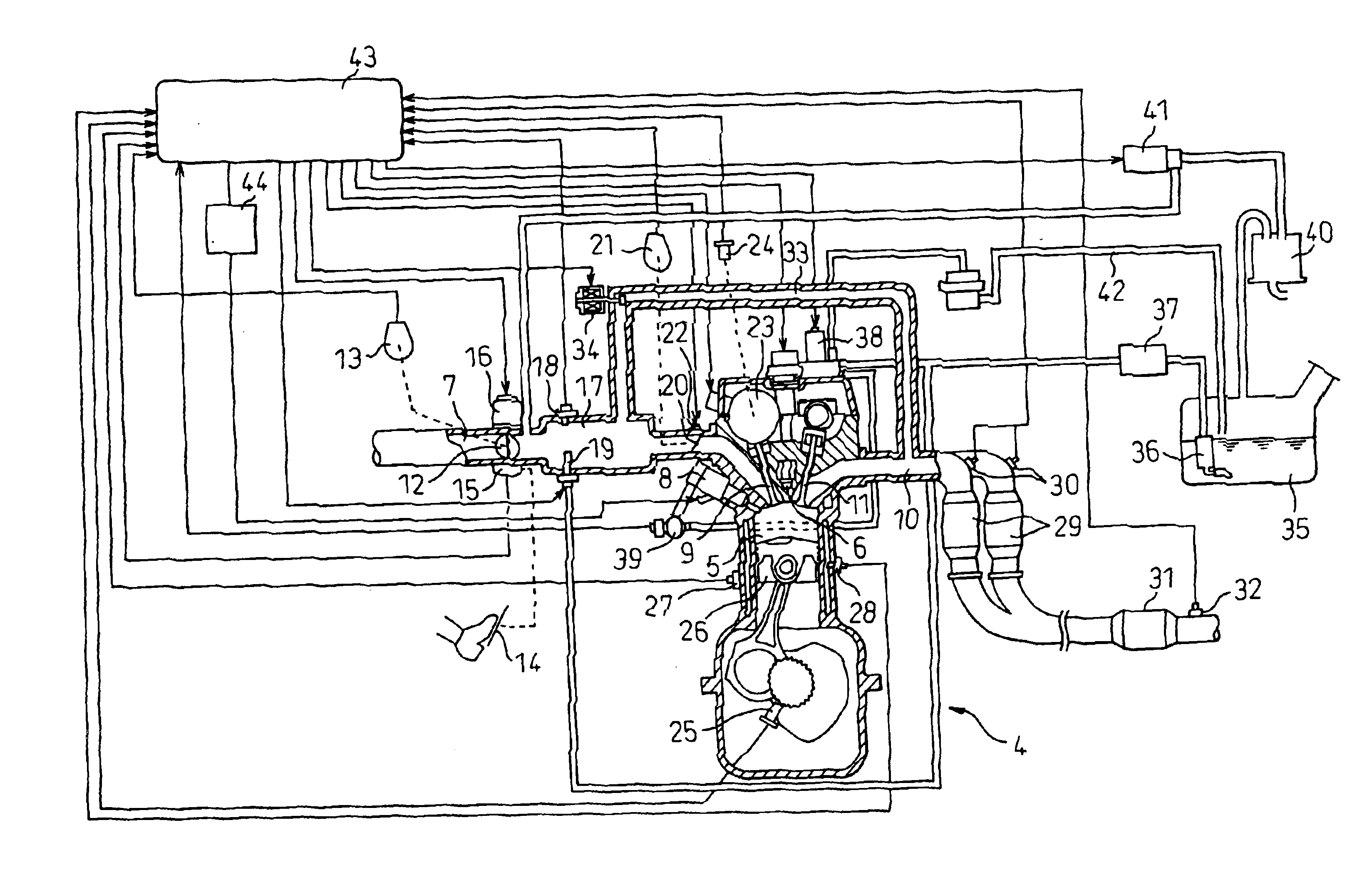
[0029]FIG. 7 is a diagram showing an internal combustion engine having an exhaust gas purification system according to the invention.

[0030]FIG. 8 is a flowchart for calculating and controlling the absorbed NOx amount according to the second embodiment of the invention.

[0031]FIG. 9 is a flowchart for controlling the start of the rich spike operation according to the second embodiment of the invention.

DESCRIPTION OF THE PREFERRED EMBODIMENTS

first embodiment

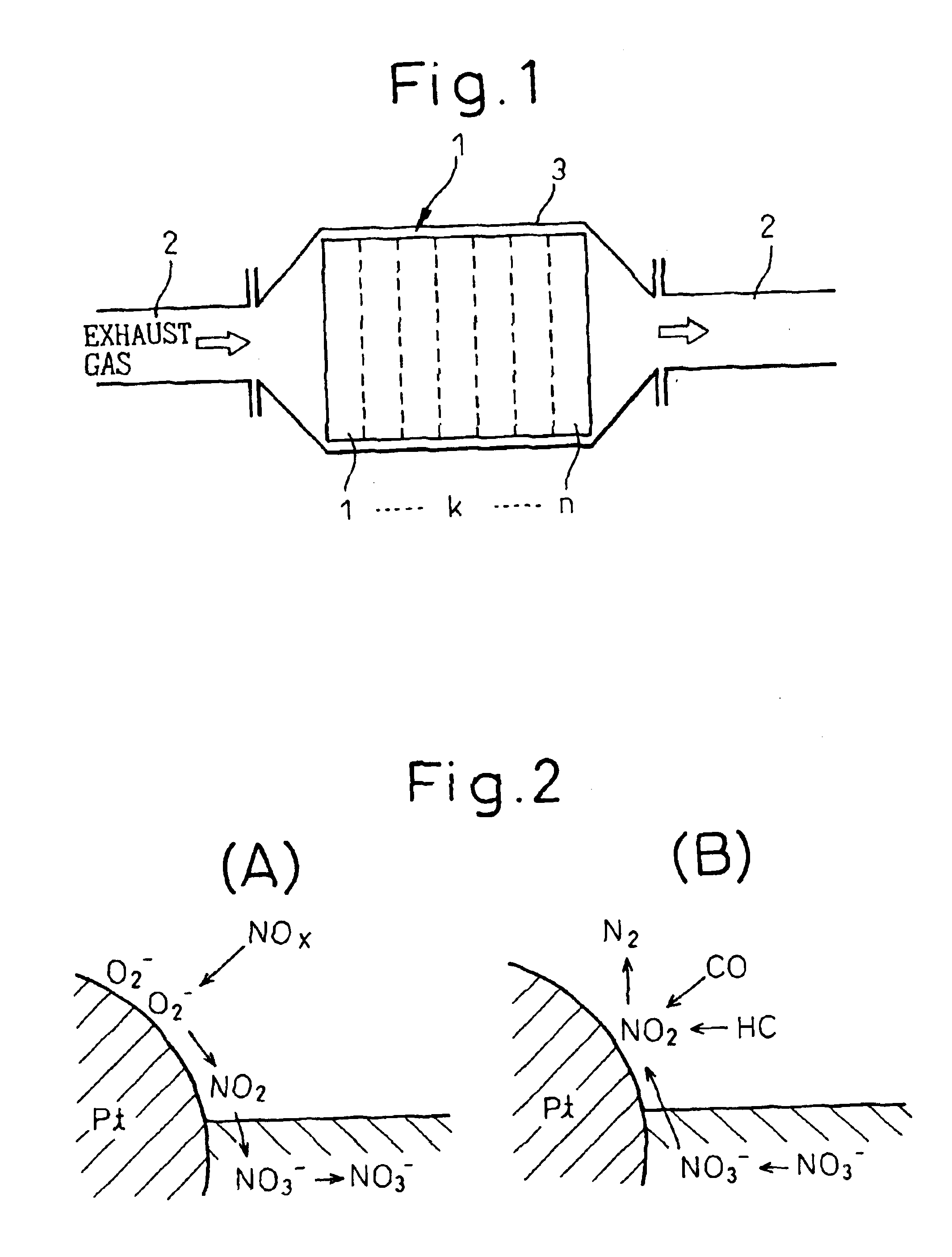
[0032]This invention will be explained below. The exhaust gas purification system according to the invention has a NOx catalyst 1 as shown in FIG. 1. If the ratio of the amount of air to the amount of the fuel (hydrocarbon) supplied into the engine intake path, the combustion chamber and the exhaust path upstream of the NOx catalyst 1 is defined as an air-fuel ratio of the exhaust gas, the NOx catalyst 1 absorbs NOx (nitrogen oxides) in the exhaust gas in the case where the air-fuel ratio of the influent exhaust gas is lean, and discharges the absorbed NOx in the case where the air-fuel ratio of the influent exhaust gas turns rich. The NOx thus discharged can be purified by being reduced with the reducing agent such as HC, CO or H2 contained in the exhaust gas.

[0033]The NOx catalyst 1 includes a NOx absorbent and a catalyst metal. The NOx absorbent is composed of alumina as a carrier, for example, for carrying at least a selected one of an alkali metal such as potassium K, sodium Na...

third embodiment

[0114]Also, when the exhaust gas of a rich air-fuel ratio is flowing into the NOx catalyst 31, or when the rich spike operation is being performed, for example, the amount of NOx discharged from the NOx catalyst 31 is calculated based on the amount of the reducing agent flowing into the NOx catalyst 31. This discharged NOx amount is subtracted from the total absorbed NOx amount to thereby obtain the total absorbed NOx amount.

[0115]Further, according to the third embodiment, as long as the rich spike operation is being performed, the amount of the reducing agent flowing into the NOx catalyst, i.e. the increment of the amount of the fuel injected from the injector 8 is controlled in such a manner that the desired amount of the reducing agent flows into the NOx catalyst based on the amount of the reducing agent flowing into the NOx catalyst.


PUM


Abstract

An exhaust gas purification system comprises a NOx catalyst for absorbing the NOx in the exhaust gas when the air-fuel ratio of the influent exhaust gas is lean and purifying by reducing the absorbed NOx with a reducing agent in the exhaust gas when the air-fuel ratio of the exhaust gas turns rich, a first unit for calculating the amount of NOx absorbed per unit time in each area of the NOx catalyst when the air-fuel ratio of the exhaust gas flowing into the NOx catalyst is lean, and a second unit for calculating the total amount of NOx absorbed into the NOx catalyst by totaling the amounts of NOx calculated by the first calculation unit for the areas of the NOx catalyst.

Description

FIELD OF THE INVENTION[0002]The present invention relates to an exhaust gas purification system for the internal combustion engine.DESCRIPTION OF THE RELATED ART[0003]A NOx catalyst is known which purifies the nitrogen oxides (NOx) contained in the exhaust gas emitted from an internal combustion engine. The NOx catalyst of a type in which the NOx in the exhaust gas flowing into the catalyst is absorbed when the air-fuel ratio of the exhaust gas is lean, and once the air-fuel ratio of the influent exhaust gas turns rich, the NOx that has been absorbed is discharged, and the NOx thus discharged is purified by being reduced with such a reducing agent as HC, CO or H2 contained in the exhaust gas, is well known.[0004]The NOx catalyst of this type is used mainly with an internal combustion engine of such a type that the combustion in the engine is carried out at a lean air-fuel ratio in most engine operating areas. In this case, as long as the exhaust gas of a lean air-fuel ratio is emitt...

Claims


Application Information

Patent Timeline
IPC IPC(8): F02D41/02F01N3/08
CPCF01N3/0842F02D41/0275F01M2250/66F02D2200/0811F02D2200/0806F01N3/08
Inventor KAKO, JUNICHINAGAI, TOSHINARIKATOH, NAOTOKATAYAMA, AKIHIROMATSUMOTO, KENTAROKOJIMA, SHINJIBABA, NAOKI
Owner TOYOTA JIDOSHA KK
Learn More