
Instrument material holder and method of fabrication thereof

a technology of material holders and holder plates, which is applied in the field of improved holders, can solve the problems of difficult to maintain tolerances of disc diameters and inside diameters of cylindrical housings, and high rejection rate of assembled material cups, and achieves the effect of less labor intensive processes

Inactive Publication Date: 2005-03-01
PERKINELMER U S LLC
View PDF15 Cites 7 Cited by
  • Summary
  • Abstract
  • Description
  • Claims
  • Application Information

AI Technical Summary

Benefits of technology

"The present invention provides a holder for materials used in measuring instruments that requires less labor-intensive processes than current methods. The holder has a reduced number of parts, facilitates reproducible and consistent performance, and accurately controls the spacing of the heater and sensor. The holder also allows for proper placement of the electron beam weld so as to prevent splattered platinum in the open cavities. The invention also provides a housing for the material holder that includes an intermediate housing member, an upper housing member, and a lower housing member. The upper and lower housing members are seated within the intermediate housing member to create a frictional fit. The holder and housing have improved reproducibility and consistent performance characteristics between material holders."

Problems solved by technology

Serious problems have been encountered in the above-described assembly and fabrication method in that it has been found to be extremely difficult to maintain tolerances on the disc diameters and the inside diameters of the cylindrical housings with sufficient precision to avoid very high rejection rates in the assembled material cups.
The high precision also requires extremely narrow tolerances in the assembled dimensions of the material holders.
On the other hand, the disc must not be press fitted with so much of an interference fit that it results in distortion of the disc.
One of the biggest problems in achieving the satisfactory press fit of the disc partitions into the cylindrical housing apparently arises because of variations in the diameters of the discs produced by the punch and die set.
Another problem in providing the correct press fit arises particularly in connection with the bottommost disc partition to which the support post is welded.
Another major problem in producing a satisfactory press fit of the disc partitions has been found to result from the fact that the electron beam welding of the first (uppermost) partition into the cylindrical housing causes the diameter of that housing to shrink slightly, so as to increase the tightness of the cylinder around the edges of subsequently assembled disc partitions.
More specifically, the processes disclosed in the '933 patent are very labor intensive to ensure proper spacing, requiring the use of precision tooling fixtures and pins.
Even when the operator is extremely careful, it difficult to accurately control the spacing of the heater and the sensor, and it is difficult to achieve reproducibility and consistent performance characteristics between material holders.
Moreover, the material holders disclosed in the '933 patent are comprised of a relatively high number of parts, and result in a high rate of scrap material (on the order of 40% to 50%) due to the fact that the heater and sensor assemblies are assembled to the center section from each end.
Furthermore, using the processes disclosed in the '933 patent, it is difficult to accurately know where to place the weld with the electron beam welder, which can result in spluttered platinum in the open cavities.

Method used


Image

  • Instrument material holder and method of fabrication thereof
  • Instrument material holder and method of fabrication thereof
  • Instrument material holder and method of fabrication thereof

Examples


Embodiment Construction

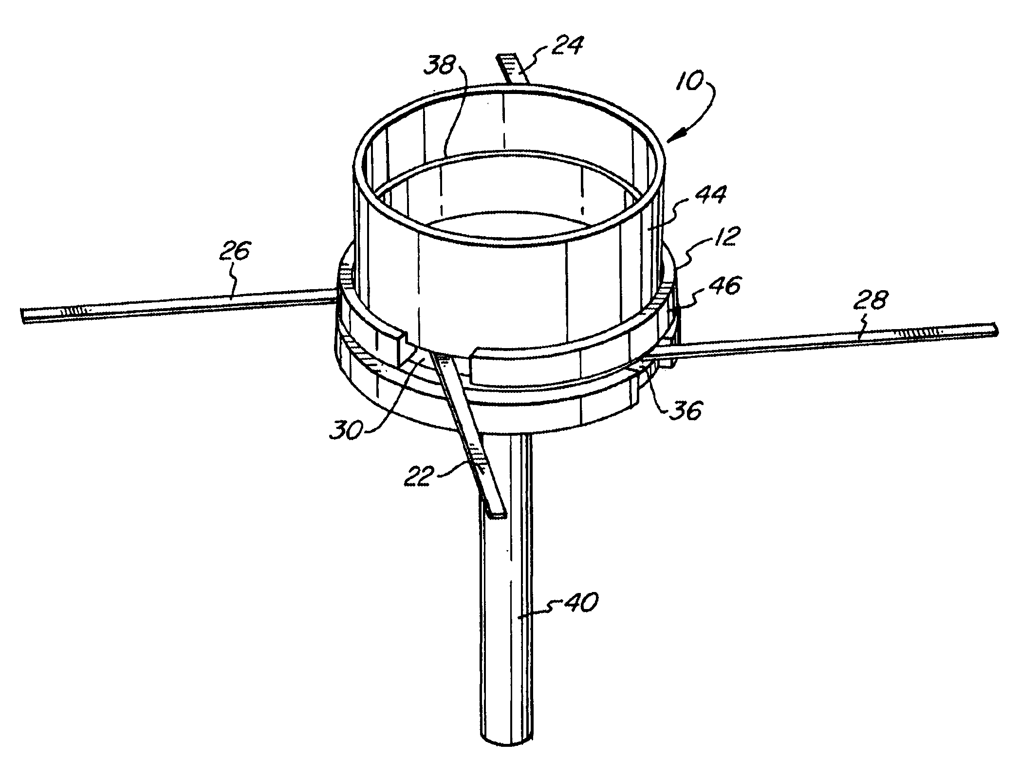
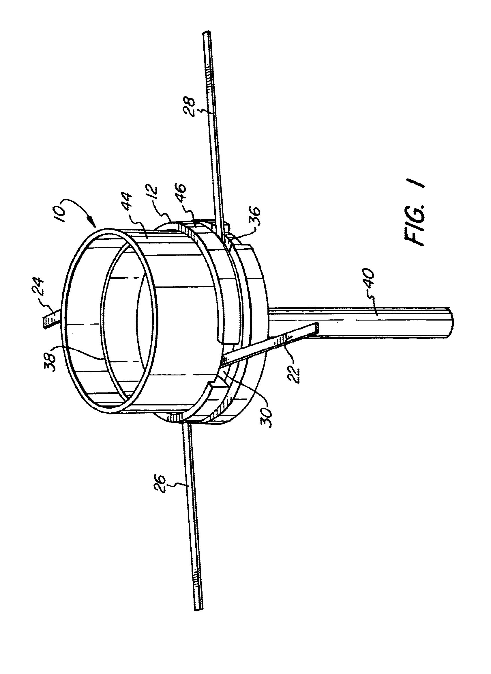
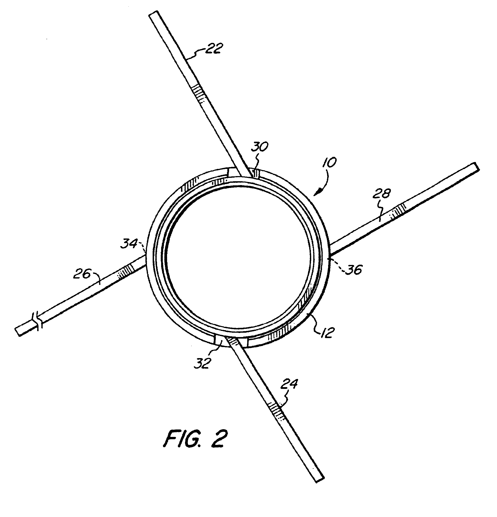
Referring first to FIGS. 1 through 4, a material holder 10 used in measuring instruments in accordance with the present invention is shown. The material holder 10 includes a housing 12 which defines a first cavity 14 and a second cavity 16, the configuration of which is described more fully below. Material holder 10 also includes a first winding assembly 18 which is intended to be housed within first cavity 14 within the material holder 10 between adjacent partitions and a second winding assembly 20 which is intended to be housed within second cavity 16 within material holder 10 between adjacent partitions.

Each winding assembly 18, 20 includes a winding holder which preferably consists of a solid aluminum oxide chip upon which a platinum wire winding is wound. A pair of platinum ribbons 22, 24 and 26, 28 are soldered to the ends of the winding of each respective winding assembly 18, 20 and serve as lead-out connectors. The lead-out connector ribbons 22, 24, 26, 28 emerge through opp...


PUM

PropertyMeasurementUnit
diameteraaaaaaaaaa
diameteraaaaaaaaaa
diameteraaaaaaaaaa

Abstract

A housing for a material holder includes an intermediate housing member having a generally horizontal member, an upper recess and a lower recess, an upper housing member having a generally horizontal member and a wall defining a material holding chamber, the upper housing member being seated within the upper recess of the intermediate housing member, and a lower housing member having a generally horizontal member, the lower housing member being seated within the lower recess of the intermediate housing member. The upper recess, the generally horizontal member of the intermediate housing member and the generally horizontal member of the upper housing member define a first cavity adapted to receive a first winding assembly, and the lower recess, the generally horizontal member of the intermediate housing member and the generally horizontal member of the lower housing member define a second cavity adapted to receive a second winding assembly.

Description

FIELD OF THE INVENTIONThe present invention relates generally to an improved holder for materials used in measuring instruments such as calorimeters and to an improved fabrication method therefor, and more particularly to an improved holder and an improved fabrication method therefor which is particularly suited for use in conjunction with a differential scanning calorimeter.BACKGROUND OF THE INVENTIONThe present invention particularly relates to a material holder used in a differential scanning calorimeter of the type disclosed and claimed in U.S. Pat. No. 3,732,722 (“the '722 patent”) for a “Material Holder” issued May 15, 1973 to Norem et al. and assigned to The Perkin-Elmer Corporation of Norwalk, Conn. The entirety of the '722 patent is incorporated by reference herein.A differential scanning calorimeter is a thermal analytical instrument which operates on the principle that thermal energy is absorbed or evolved during physical or chemical changes in a material which is being a...

Claims


Application Information

Patent Timeline
Patent Type & Authority Patents(United States)
IPC IPC(8): G01N25/20G01N25/48
CPCG01N25/486
Inventor GROESCHNER, DONALD L.
Owner PERKINELMER U S LLC
Learn More