Polyelectrolyte derivatization of microfluidic devices

a microfluidic device and polyelectrolyte technology, applied in the direction of fluid pressure measurement, liquid/fluent solid measurement, peptide measurement, etc., can solve problems such as complex flow patterns, and achieve the effect of enhancing the biocompatibility of plastic microchannels and derivatizing the wettability of microchannels

Inactive Publication Date: 2005-03-01
GOVERNMENT OF THE US REPRESENTED BY THE SEC OF COMMERCE THE
View PDF5 Cites 24 Cited by
  • Summary
  • Abstract
  • Description
  • Claims
  • Application Information

AI Technical Summary

Benefits of technology

One key feature of the present invention relates to altering the charge on the surfaces of a microchannel via PEM derivatization. Through PEM derivatization of a variety of different substrate materials which have different native EOF mobilities, similar EOF rates now can be achieved in microchannels formed in a variety of different materials. Thus, the present invention provides the advantage of the use of different materials while maintaining a similar EOF rate which was not easily achieved using underivatized (i.e., native) plastic materials.
Another feature is to increase biocompatibility of plastic microchannels in a generic way using PEMs.
A further feature of the present invention relates to enhanced wettability of microchannels derivatized using PEMs. As a result, priming the microchannel before introducing a fluid sample becomes unnecessary. Further, air bubbles are less likely to get pinned on the microchannel surface of the derivatized microchannels.
Yet another feature of the PEMs coated microchannel walls of the present invention is the ability to attach other molecules to the microchannel wall. Such immobilization allows for attachment or entrapment of molecules such as proteins, antibodies and DNA to the walls of a microchannel formed in a variety of substrates.

Problems solved by technology

Further, complex flow patterns, including flow in opposite directions in the same microchannel, can be generated in a microchannel with opposing surfaces having opposite charges.

Method used


Image

  • Polyelectrolyte derivatization of microfluidic devices
  • Polyelectrolyte derivatization of microfluidic devices
  • Polyelectrolyte derivatization of microfluidic devices

Examples


Embodiment Construction

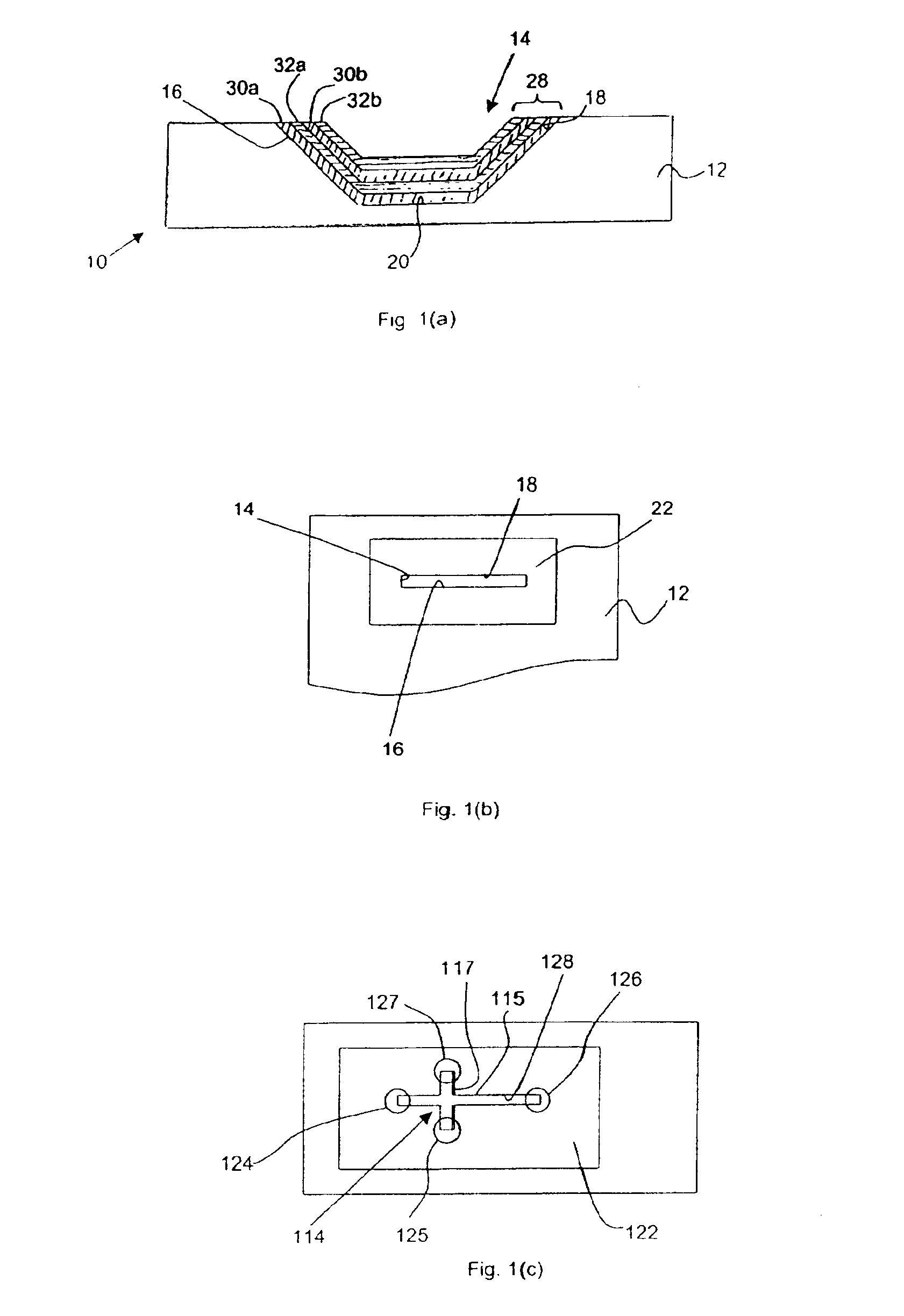
Referring now to the figures, and in particular, to FIGS. 1(a) and 1(b), microfluidic device 10 comprises a plastic substrate 12. The plastic substrate 12 may be composed of any suitable plastic or polymer material which includes but is not limited to polystyrene (PS), poly(ethylene terephthalate glycol) (PETG), poly(methyl methacrylate) (PMMA), and polycarbonate (PC).

A microchannel 14 formed in substrate 12 has a trapezoidal cross-section defined by slanted sidewalls 16, 18. Alternatively, the side wall surfaces of the microchannel 14 could be substantially perpendicular to a bottom surface 20. Alternatively, the microchannel could have sloped side walls, straight side walls without a well defined floor (V groove) or curved, semicircular side walls forming a “U-shaped” groove, or any other configuration with a channel that has one or more spatial dimensions in the micrometer size range. The depth of microchannel 14 is between 0.05 and 1000 μm and optimally between 1 and 100 μm. The...


PUM

PropertyMeasurementUnit
depthaaaaaaaaaa
depthaaaaaaaaaa
depthaaaaaaaaaa

Abstract

A microchannel device is provided with a plastic substrate having a microchannel formed therein. Polyelectrolyte multilayers are disposed along selected surfaces of the microchannel. The polyelectrolyte layers comprise alternating net positively charged layers and net negatively charged layers. A microchannel lid has a surface facing the microchannel. In making the microchannel device, selected surfaces of the microchannel are alternatively exposed to solutions comprising positively charged polyelectrolytes and negatively charged polyelectrolytes to form the desired number of polyelectrolyte layers.

Description

BACKGROUND OF THE INVENTION1. Field of the InventionThe present invention relates to a microchannel device, and in particular, a microchannel device comprising a microchannel having microchannel wall surfaces with polyelectrolyte multilayers of alternate charge formed thereon.2. Background of the InventionIn the past few years, there has been an increasing interest in the field now generally known as microfluidics. An important challenge in developing the first generation of microanalytical systems is in the successful design and fabrication of microcapillary channels and networks formed thereof, collectively referred to as microchannels. The microchannels may be composed of intersecting subchannels thereby forming a plurality of microchannel arms. These microchannels may be ultimately incorporated into self-contained analytical systems with detection and processing elements for use to perform chemical or biochemical measurements. Fluid transport in the microchannels may be accompli...

Claims


Application Information

Patent Timeline
Patent Type & Authority Patents(United States)
IPC IPC(8): B32B3/18B32B3/20G01N27/447
CPCB32B3/20G01N27/44704G01N27/44791G01N27/44752Y10T428/24562
Inventor LOCASCIO, LAURIE E.BARKER, SUSAN L. R.ROSS, DAVIDTARLOV, MICHAEL J.
Owner GOVERNMENT OF THE US REPRESENTED BY THE SEC OF COMMERCE THE
Why Eureka
Try Eureka