
Magnetic detection element utilizing magneto-impedance effect, production method of the element, and portable equipment using the element

a technology of magneto-impedance effect and magnetic detection element, which is applied in the field of magnetic detection element, can solve the problems of severe constraints in designing components, the demand for “real estate”, and the increase in the volume of the element, and achieve the effect of not sacrificing the siz

Inactive Publication Date: 2005-03-01
CANON DENSHI KK
View PDF36 Cites 13 Cited by
  • Summary
  • Abstract
  • Description
  • Claims
  • Application Information

AI Technical Summary

Benefits of technology

The present invention provides an element structure for a magnetic detection device that allows for stable device characteristics without sacrificing size. The structure includes a magnetic thin film formed on a non-magnetic substrate, a circuit that applies a high-frequency current to the film, and a spiral planar coil stacked on the film through an insulating layer. The magnetic thin film is formed in a longitudinal shape with magnetic anisotropy, and the direction of easy magnetization axis is made orthogonal to the longitudinal direction. The production method involves forming a magnetic thin film on a substrate, giving it a predetermined magnetic characteristic through heat treatment in a magnetic field, adding an insulating film, and then forming a spiral coil pattern made of a conductive metal material on the insulating film.

Problems solved by technology

However, since high-density mounting has been required in connection with the miniaturization of portable equipment, the demand for area and height (the demand for “real estate”, and the constraints to be met in designing components in order for them to fit within the space available) has become severe.
However, in the bias coil 115 externally mounted as shown in FIG. 14, it is not possible to make effective use of the element size (miniaturize it to the degree that would be desirable as discussed above), and hence, it is not possible to use such a coil as a space-saving component for portable equipment or the like.
Hence, due to property degradation by stress warpage between materials through an insulating layer 118 and limitations on temperature conditions imposed by the thermal resistance of the insulating layer 118, it becomes difficult to obtain the necessary characteristics of the magnetic thin film.
Specifically, since the insulating film 118 and a coil conductive layer 116a are inserted between the magnetic thin film 112 and non-magnetic substrate 110 in FIG. 17, it is difficult to control the stress to which the magnetic thin film is subjected, and it is also difficult to obtain optimal conditions for the magnetic characteristics.
In addition, limitations such as impossibility of temperature increase to 500° C. or higher arise in heat treatment, which tends to result in anisotropy in the magnetic characteristics.
Even in the case of such structure, however, there is a similar problem.

Method used


Image

  • Magnetic detection element utilizing magneto-impedance effect, production method of the element, and portable equipment using the element
  • Magnetic detection element utilizing magneto-impedance effect, production method of the element, and portable equipment using the element
  • Magnetic detection element utilizing magneto-impedance effect, production method of the element, and portable equipment using the element

Examples


embodiment 1

(Embodiment 1)

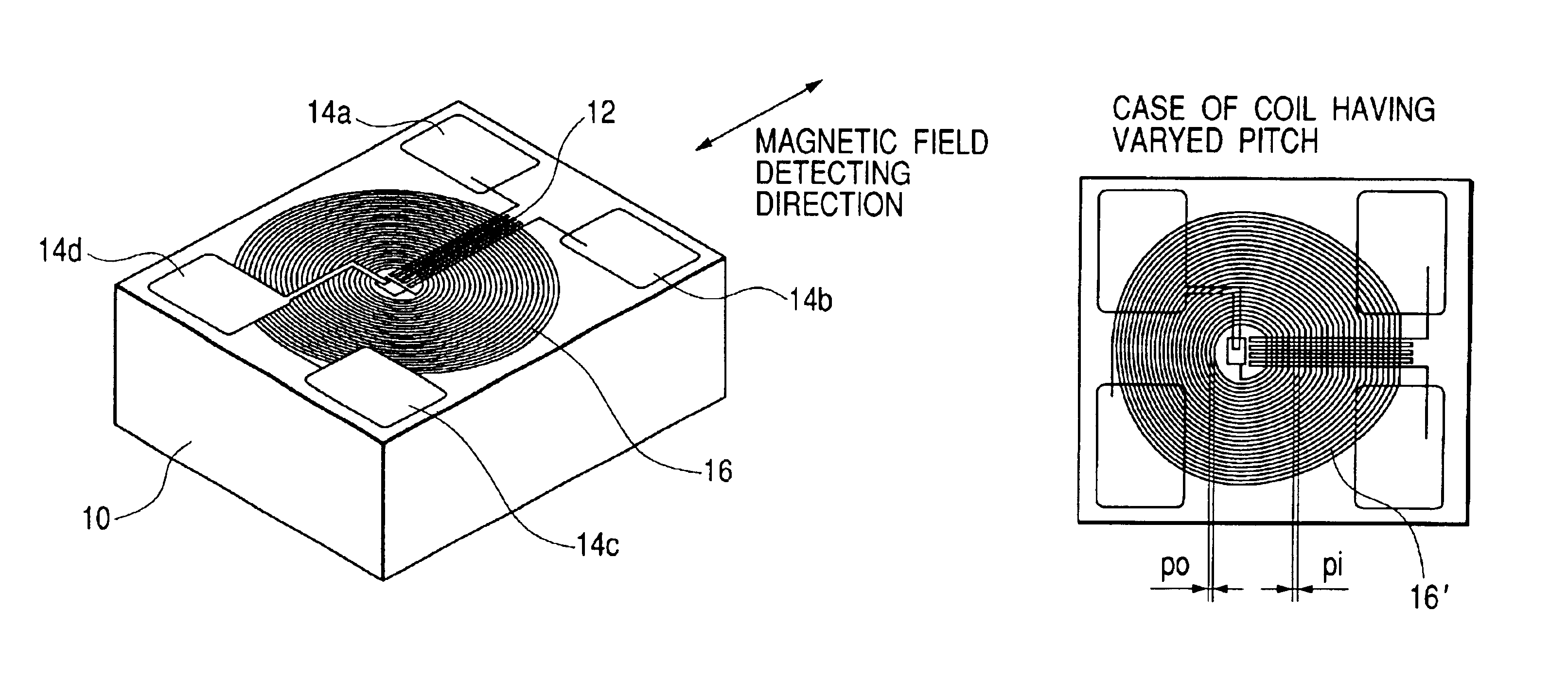
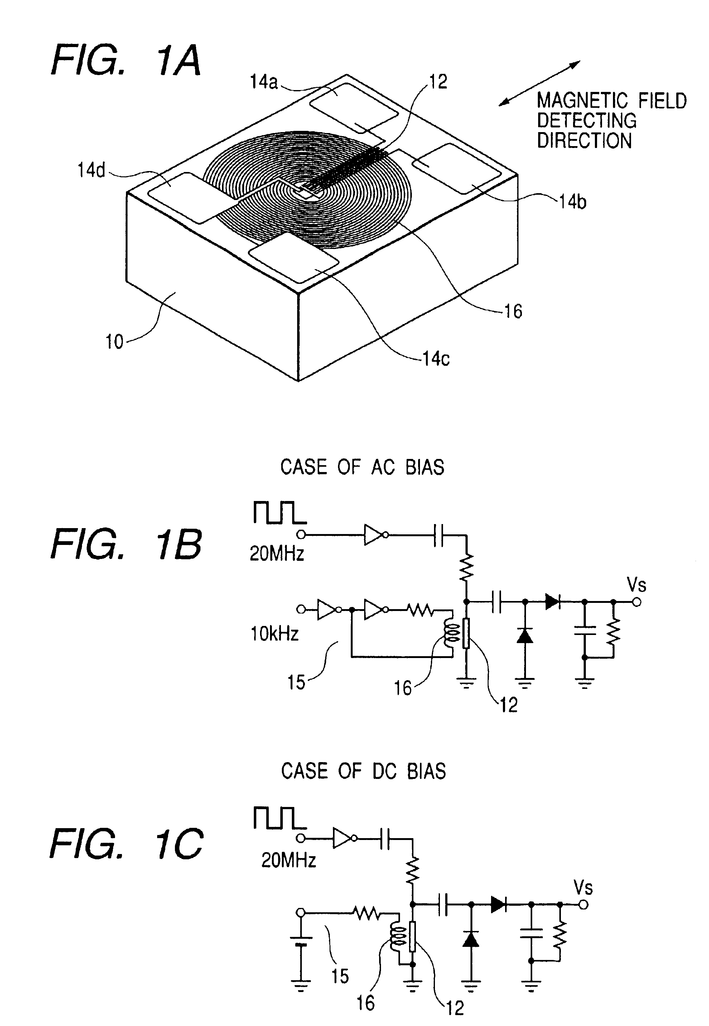
A first embodiment is shown in FIGS. 1A to 1C.

A magnetic detection portion 12 that has a structure formed by folded magnetic thin film patterns, which are slender and are arranged parallel to each other, on a single non-magnetic substrate 10 made of a glass or the like, and both ends of the magnetic detection portion 12 are connected to electrodes 14a and 14b. The magnetic field detecting direction of the magnetic detection portion is a longitudinal direction of the patterns, as shown by an arrow in the figure. In addition, the magnetic detection portion is given magnetic anisotropy such that the direction (axis) of easy magnetization is orthogonal to the longitudinal direction. On the magnetic detection portion 12, sandwiching a first insulating layer, a flat spiral coil 16 is arranged so that its center coincides with an end of the magnetic field detection portion 12. Both ends of the above-described coil are connected to electrodes 14c and 14d, sandwiching a second ...

embodiment 2

(Embodiment 2)

In the above-mentioned first embodiment, the structure of detecting the amplitude and direction of an external magnetic field by applying a high-frequency current to a magnetic body, and detecting an impedance change between both ends thereof is shown. However, it is also good to make the structure of detecting the amplitude and direction of an external magnetic field by applying a high-frequency current to a magnetic body, and detecting an induced voltage change generated in a spiral coil according to the external magnetic field. In this case, the spiral coil is not used for bias magnetic field application, but for induced voltage detection.

Its specific structure will be explained by using FIG. 9.

Similarly to the conventional, a pulse-oscillated current is applied to the electrodes 14a and 14b, of the magnetic detection portion 12 of the element by an oscillation circuit 217. As a waveform is shown in FIG. 10, a pulse voltage output with peaks corresponding to the ris...

embodiment 3

(Embodiment 3)

Next, an embodiment of portable equipment where the magnetic detection element is built, as explained in the above-mentioned embodiment, will be explained. When two magnetic detection elements are used and arranged so that respective magnetic field detecting directions may be orthogonal, it is possible to take out signals corresponding to respective external magnetic fields in two orthogonal directions from respective magnetic field detecting elements. Using this, it is possible to constitute a magnetic sensor device that detects external magnetic fields in two directions, for example, an azimuth sensor that detects components of the magnetic fields in terrestrial magnetism in the X-and Y-directions orthogonal to each other, and detects an azimuth angle based on the direction of the terrestrial magnetic vector (- and S-directions that a magnetic needle of a compass indicates).

In this embodiment, examples of combining two magnetic detection elements of the present inven...


PUM


Abstract

A magnetic detection element suitable for detecting a strength of an external magnetic field, has a magnetic thin film formed on a single non-magnetic substrate, a circuit that applies a high-frequency current to the magnetic thin film, and a spiral-type planar coil that is stacked on the magnetic thin film with an insulating layer, in between. The magnetic thin film is formed in a longitudinal shape, and magnetic anisotropy is provided such that the direction of easy magnetization is orthogonal to the longitudinal direction of the longitudinal shape.

Description

BACKGROUND OF THE INVENTION1. Field of the InventionThe present invention relates to a magnetic detection element that uses a magneto-impedance element comprising a magnetic body as a magnetic detection portion in which impedance between both ends of the magnetic body changes according to an external magnetic field when a high-frequency current is applied to the magnetic body. The invention also relates to a method of producing such element, and portable equipment equipped with the element.2. Related Background ArtRecently, since small information terminal functions of mobile phones, PDAs and the like have been developed, needs of displaying the magnetic azimuth have increased in map information display, GPS mounting, etc.However, since high-density mounting has been required in connection with the miniaturization of portable equipment, the demand for area and height (the demand for “real estate”, and the constraints to be met in designing components in order for them to fit within ...

Claims


Application Information

Patent Timeline
Patent Type & Authority Patents(United States)
IPC IPC(8): G01C17/00G01C17/30G01R33/02H01L43/00H01L43/02
CPCG01R33/02G01C17/30
Inventor KAWASE, MASAHIRO
Owner CANON DENSHI KK
Learn More