Voltage-controlled oscillator with LC resonant circuit

a voltage-controlled oscillator and resonant circuit technology, applied in the direction of instruments, pulse techniques, discontnuous tuning with seperate pre-tuned circuits, etc., can solve problems such as continuous frequency tunability

Inactive Publication Date: 2005-03-01
IHP GMBH INNOVATIONS FOR HIGH PERFORMANCE MICROELECTRONICS LEIBNIZ INST FUR INNOVATIVE
View PDF9 Cites 27 Cited by
  • Summary
  • Abstract
  • Description
  • Claims
  • Application Information

AI Technical Summary

Benefits of technology

The teaching of the invention involves replacing the coils in a resonant circuit by pairs of coils which are connected in parallel and/or in series and of which a respective one of the coils is connected to a switch which is periodically opened and closed. That means that in each case only one coil or the p...

Problems solved by technology

This results in the desired...

Method used


Image

  • Voltage-controlled oscillator with LC resonant circuit
  • Voltage-controlled oscillator with LC resonant circuit
  • Voltage-controlled oscillator with LC resonant circuit

Examples


example 2

As a further embodiment by way of example FIG. 3 shows a circuit arrangement of the oscillator according to the invention with two respective first inductors L1, L3, in relation to each of which a further respective inductor L2 can be connected in parallel.

The frequency tuning range can be increased by the use of more than two inductors L1, L2, as demonstrated in FIG. 3.

example 3

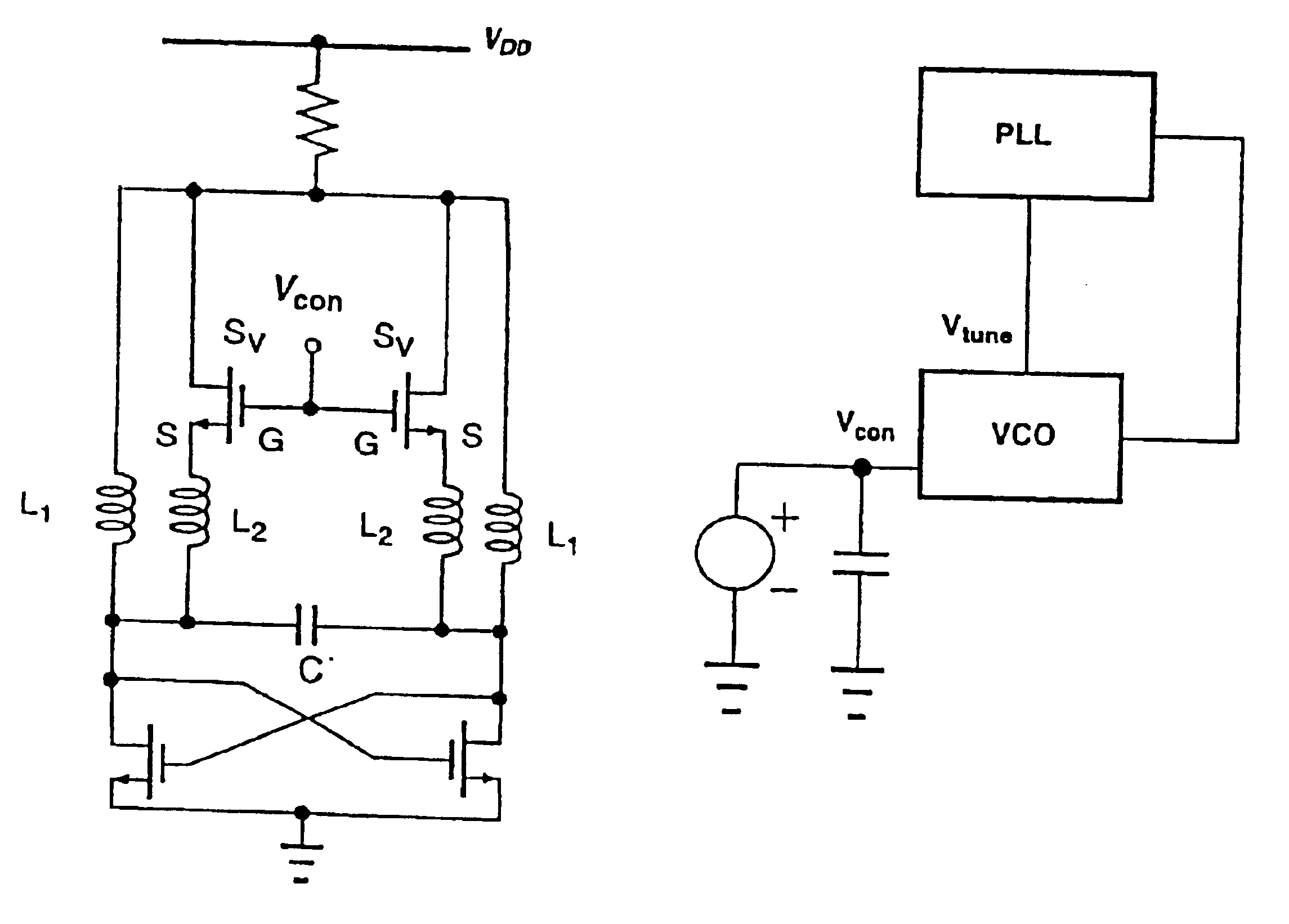
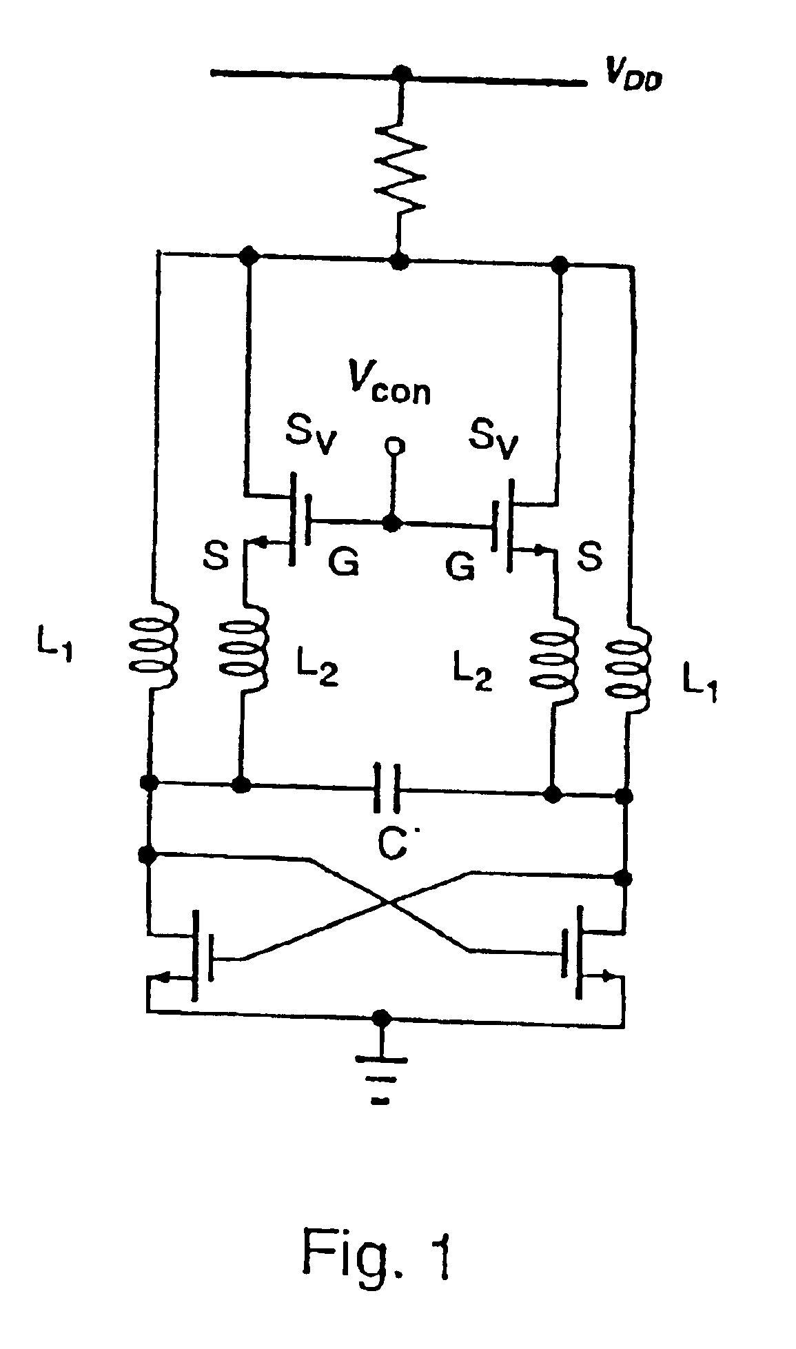
FIG. 4 shows an LC-oscillator according to the invention with two co-operating semiconductor switches and a capacitor C. The inductors L1 are arranged in two branches. Associated with each of the two inductors L1 is a respective further inductor L2 which can be connected in series with the first inductors L1 by a respective switching means Sv. The gate terminals G of the switching means Sv which are in the form of MOSFETs are connected to an input Vcon for a control voltage Ucon while the source terminals S are connected to the output of the oscillator, which carries the oscillator frequency.

When the switching means Sv is closed the total inductance is of a lower value than when the switching means Sv is opened. The switching means Sv is modulated at the oscillation frequency.

The mode of operation of the oscillator according to the invention is as follows: the two switching means Sv, in this embodiment being two MOSFETs, are opened with a low voltage Ucon at the input Vcon during th...

example 4

FIG. 5 shows a combination of inductive and capacitive tuning. Besides inductive tuning, capacitive tuning is also possible.

Inductive tuning is based on the principle described in the preceding embodiments. In this embodiment the inductors L1 and L2 are connected in parallel. The two switching means Sv are opened at a low control voltage Ucon at the input Vcon during the major part of an oscillation period of the oscillator. That state occurs as long as the gate-source voltage does not exceed the switching point of the switching means Sv. During the duration of the non-conducting state of the switching means Sv only the first inductors L1 are effective. For a small part of the oscillation period the gate-source voltage exceeds the switching point of the switching means Sv. For the duration of the now conducting state of the switching means Sv the further inductors L2 are connected in parallel with the first inductors L1 whereby the total value of the effective inductance decreases a...


PUM


Abstract

A voltage-controlled oscillator device with an LC-resonant circuit, in particular for implementing integrated voltage-controlled oscillators for the lower GHz range, is disclosed. The device achieves continuous frequency tunability in a wide range in particular with a low level of phase noise and phase jitter. In the voltage-controlled oscillator, a second inductor can be periodically switched in parallel and/or in series with at least one first inductor of the LC-resonant circuit by way of a switching means actuated with the oscillator frequency. A control input of the switching means is connected to a variable dc voltage. In that respect the relationship of the duration of the conducting state and the duration of the non-conducting state of the switching means is variable within an oscillation period of the oscillator in dependence on the value of the control voltage. In accordance with the relationship of the duration of the conducting state and the duration of the non-conducting state of the switching means within an oscillation period of the oscillator the time-averaged effective inductance is variable in dependence on the value of the control voltage.

Description

The invention concerns a voltage-controlled oscillator with an LC-resonant circuit, in particular for implementing integrated voltage-controlled oscillators for the lower GHz range.BACKGROUND OF THE ARTIntegrated circuits involve using voltage-controlled oscillators which are mostly in the form of ring oscillators or LC-oscillators. Ring oscillators are distinguished by a high degree of frequency tunability. That advantage however is impaired by a strong phase noise and a severe phase jitter. In the case of LC-oscillators frequency tunability is predominantly implemented by means of variable capacitors, for example capacitor diodes. Those oscillators admittedly involve a lower level of phase noise and a lesser degree of phase jitter, but frequency tunability is in most cases seriously reduced.Japanese patent application 093 215 38 A describes a voltage-controlled LC-oscillator circuit in which a part of the inductance is short-circuited by means of a switching transistor for given p...

Claims


Application Information

Patent Timeline
IPC IPC(8): H03K3/354H03K3/00H03L7/099H03L7/08H03B5/08H03B5/12H03B1/00
CPCH03K3/354H03L7/099H03B5/1293H03B5/1268H03B5/1215H03B5/1253H03B5/1228H03B2201/0216H03L2207/06
Inventor HERZEL, FRANKWEGER, PETER
Owner IHP GMBH INNOVATIONS FOR HIGH PERFORMANCE MICROELECTRONICS LEIBNIZ INST FUR INNOVATIVE
Why Eureka
Try Eureka