Code modulating method and code modulating apparatus, demodulating method and demodulating apparatus, and information recording medium

a code modulating and code technology, applied in the field of demodulating methods and demodulating apparatuses, can solve the problems of channel bit detection difficulty, jitter, and fluctuation of servo control signals of disk devices, so as to prevent the occurrence of detecting errors, prevent the influence of over three bytes, and prevent the effect of low frequency components

Inactive Publication Date: 2005-03-01
NEC CORP +1
View PDF9 Cites 21 Cited by
  • Summary
  • Abstract
  • Description
  • Claims
  • Application Information

AI Technical Summary

Benefits of technology

According to the present invention, it is possible to provide a code modulating method and a code modulating apparatus for obtaining a modulating code which has an encoding rate equal to that of (1, 7) modulation, prevents the existence of a pattern facilitating a detecting error of a reproduction signal in a channel bit train, and is suitable to high-density recording having low DC components. In addition, a demodulating method and a demodulating apparatus according to the present invention is for use in reading the above code and an information recording medium records data by using the code and prevents the occurrence of the detecting error. Specifically, a channel bit train according to the present invention has an encoding rate of ⅔, a minimum value of the run length 1, a maximum value 10, and the repeat times of the run length 1 not greater than five times. Further, the channel bit train has a sufficiently low frequency component and is suitable to the high-density recording. In view of the boundary of the code word, advantageously, the influence over three bytes is prevented. Furthermore, the encoding rate is ⅔ and the amplitude strength is lower than a maximum value thereof by 20 dB at the frequency of {fraction (1 / 10,000)} or less of the channel clock frequency. On the contrary, in the demodulation, the data is processed based on the code word unit of 12 channel bits. Further, the code word just after / before it may be referred to and the circuit structure is realized without propagating the detecting error. In addition, advantageously, the channel clock is stably extracted even with high recording density, and the detecting error does not occur.

Problems solved by technology

On recordation or reproduction of data on or from the recording medium, DC components included in signals or codes recorded or reproduced are liable to cause fluctuation of a servo control signal of a disk device to occur, or to cause jitters to occur.
Herein, it has been pointed out that, in a reproduction signal recorded with a high density in a disk, detection of the channel bit becomes difficult because a signal amplitude becomes small due to a short pattern of mark and space lengths.
The reduction of the amplitude is liable to increase jitters due to noises when a reproduction signal is converted into binary data by the use of a comparator.
In the PRML detection, a detection error therefore frequently occurs in the reproduction signal which includes continuous patterns of 2T.
However, in the portion which has the continuous patterns of 2T, it is difficult to specify the phase of the channel bit train only on the basis of the reproduction waveform in the above-mentioned portion.
Mixture of the noise in the reproduction waveform tends to cause a detection error to occur in the case where detection is made in the state of shifting a whole of continuous patterns of 2T by one channel bit length of T in a long continuous portion of 2T.
This makes it difficult to extract a channel clock from the reproduction signal.
However, no teaching is made at all about the problems caused by the continuous state of the minimum run length 1 and its solving means.
In addition, it is disadvantageous on reproducing, from the disk, the signal recorded by using the (1, 7) modulation a low frequency component is included in the reproduction signal.
Further, the low frequency component in the reproduction signal undesirably varies a servo control signal for controlling a disk device.

Method used


Image

  • Code modulating method and code modulating apparatus, demodulating method and demodulating apparatus, and information recording medium
  • Code modulating method and code modulating apparatus, demodulating method and demodulating apparatus, and information recording medium
  • Code modulating method and code modulating apparatus, demodulating method and demodulating apparatus, and information recording medium

Examples


Embodiment Construction

To clarify the above and other objects, features, and advantages according to the present invention, embodiments of the present invention will be described in detail with reference to the attached drawings.

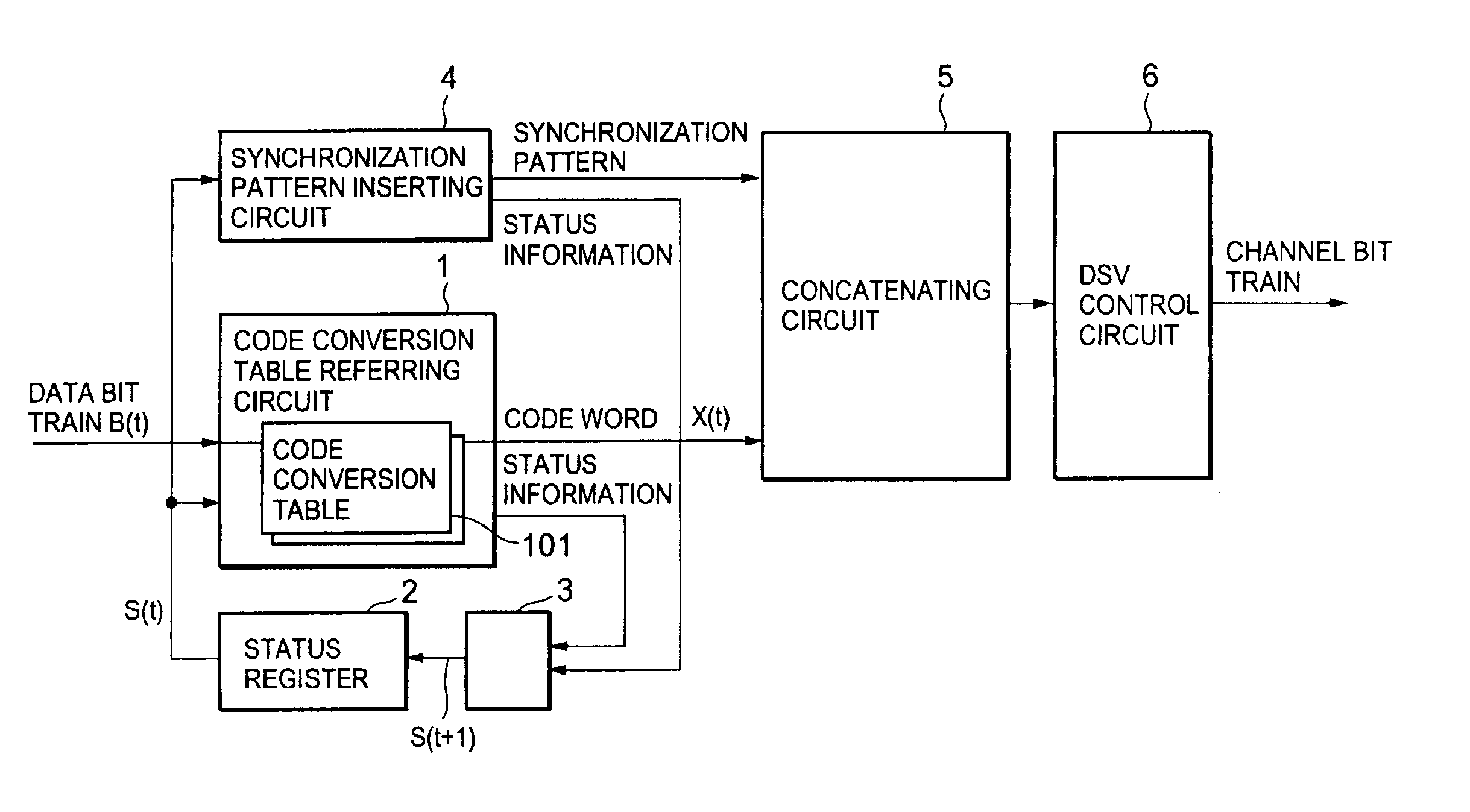
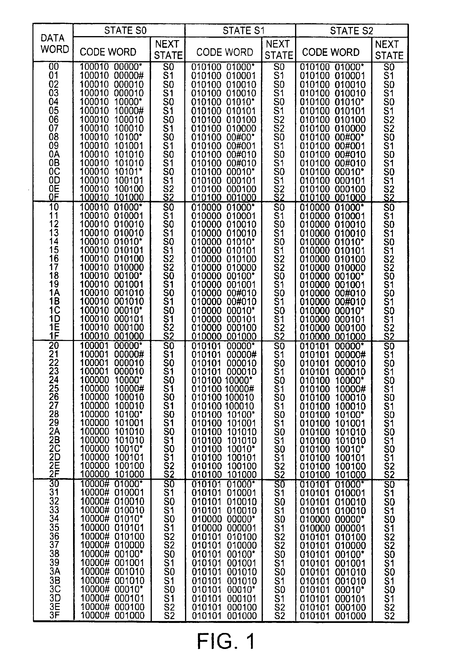
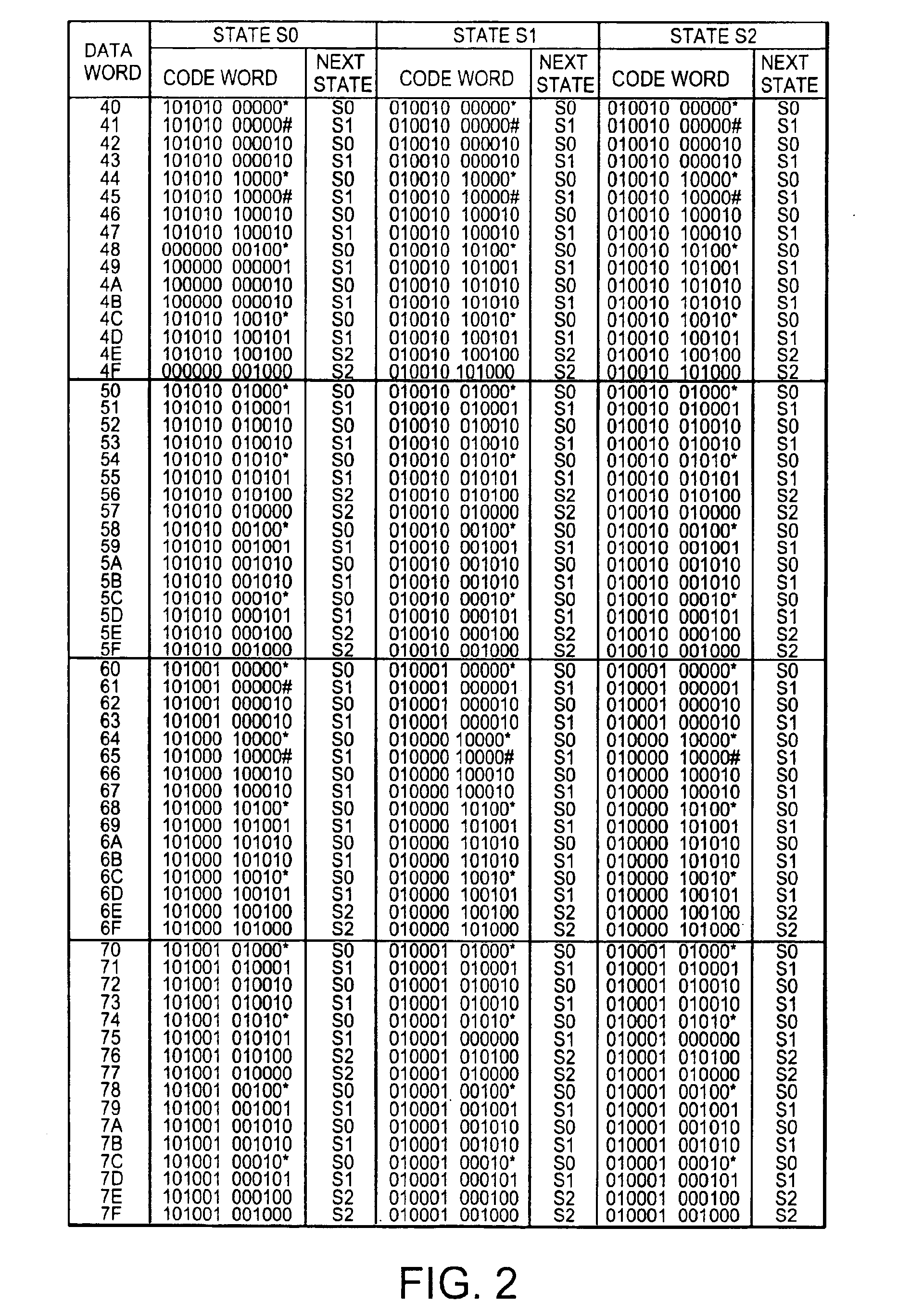
FIGS. 1 to 4 show code conversion tables for use in a code modulating method according to the first embodiment of the present invention. In FIGS. 1 to 4, data words of 8 bits 00 to FF are expressed by hexadecimal representations together with corresponding code words of twelve (12) channel bits and next or subsequent states represented by S0 to S2. In each figure, the above-mentioned data words, the code words, and the next states are collectively illustrated in the form of the tables. From this fact, it is readily understood that the code modulation according to the present invention is for modulating the data words of eight (8) bits into the channel bits of twelve (12) bits and carries out eight to twelve ({fraction (8 / 12)}) modulation of the encoding rate (⅔).

Specifically, the ...


PUM

PropertyMeasurementUnit
run lengthaaaaaaaaaa
frequencyaaaaaaaaaa
power densityaaaaaaaaaa

Abstract

In a code modulating method and a code modulating apparatus, a run length has an encoding rate of ⅔ which is equal to that of (1, 7) modulation, and indicates the number of “0” bits between adjacent ones of “1” bits in the channel bit train. A data bit train is converted into the channel bit train so that the run length has a minimum value 1 and a maximum value 10. Further, upon converting any data bit train, the channel bit train does not include a pattern “1010101010101” in which the run length 1 is continuously repeated six times or more. The channel bit train has a DSV (Digital Sum Value) control bit which selects the “0” bit or “1” bit in accordance with a DSV. The channel bit train obtained by using random data for the data bit train is NRZI converted into a signal. A frequency component of the signal is reduced from a maximum value of the frequency component by 20 dB or less as a power density at a frequency of {fraction (1/10,000)} or less of a channel clock frequency.

Description

BACKGROUND OF THE INVENTION1. Field of the InventionThe present invention relates to a code modulating method and a code modulating apparatus, a demodulating method and a demodulating apparatus, and an information recording medium, all of which are used for recording or reproducing digital data on a recording medium, such as an optical disk.2. Description of the Related ArtOn recording data on a recording medium, such as an optical disk, data modulation is carried out so as to be matched with the recording medium. On recordation or reproduction of data on or from the recording medium, DC components included in signals or codes recorded or reproduced are liable to cause fluctuation of a servo control signal of a disk device to occur, or to cause jitters to occur. Therefore, it is preferable that modulation signal or codes include no DC components, if possible.A DVD (Digital Versatile Disc) uses eight to sixteen ({fraction (8 / 16)}) modulation which modulates an 8-bit data bit train in...

Claims


Application Information

Patent Timeline
Patent Type & Authority Patents(United States)
IPC IPC(8): G11B20/14G11B27/30H03M7/14
CPCG11B20/1426G11B27/3027G11B2220/2562G11B2020/1457
Inventor KAYANUMA, KINJIIWANAGA, TOSHIAKINODA, CHOSAKU
Owner NEC CORP
Why Eureka
Try Eureka