In-cycle shuffle

a technology of in-cycle shuffle and control bundle, which is applied in the direction of nuclear power plant control, nuclear elements, greenhouse gas reduction, etc., can solve the problems of limiting the thermal performance of the controlled bundle, and achieve the effect of reducing unanticipated problems, increasing energy output, and increasing revenue over operating plans

a technology of in-cycle shuffle and control bundle, which is applied in the direction of nuclear power plant control, nuclear elements, greenhouse gas reduction, etc., can solve the problems of limiting the thermal performance of the controlled bundle, and achieve the effect of reducing unanticipated problems, increasing energy output, and increasing revenue over operating plans

US6862329B1Active Publication Date: 2005-03-01GLOBAL NUCLEAR FUEL -- AMERICAS

Image

  • In-cycle shuffle
  • In-cycle shuffle
  • In-cycle shuffle

Examples


Embodiment Construction

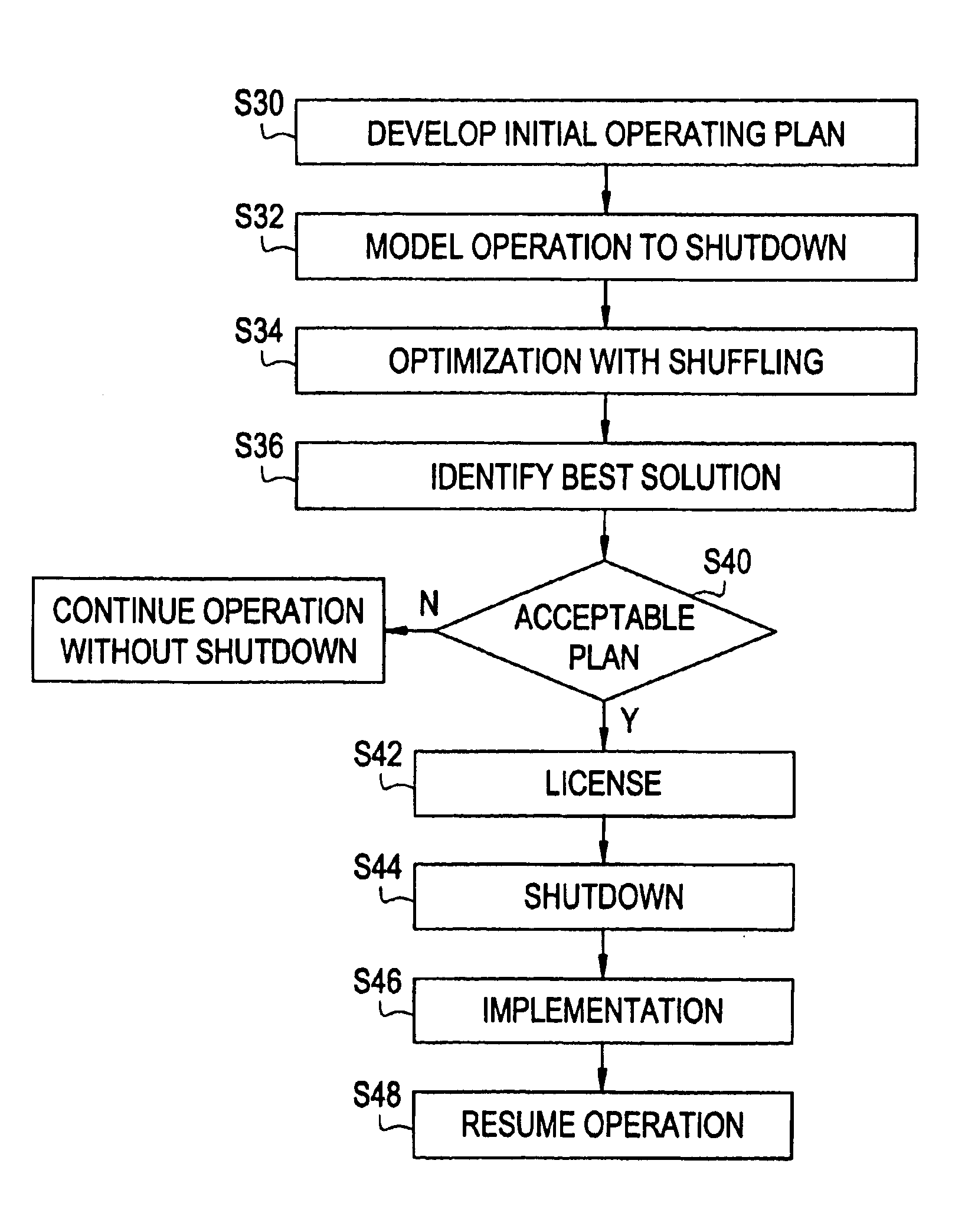
First a method of developing an operating plan will be described in detail. Then, the method of improving reactor performance through in-cycle shuffling according to the present invention will be described.

Creating an Operating Plan

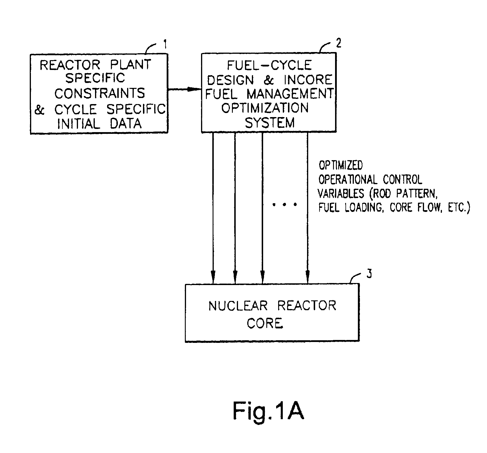
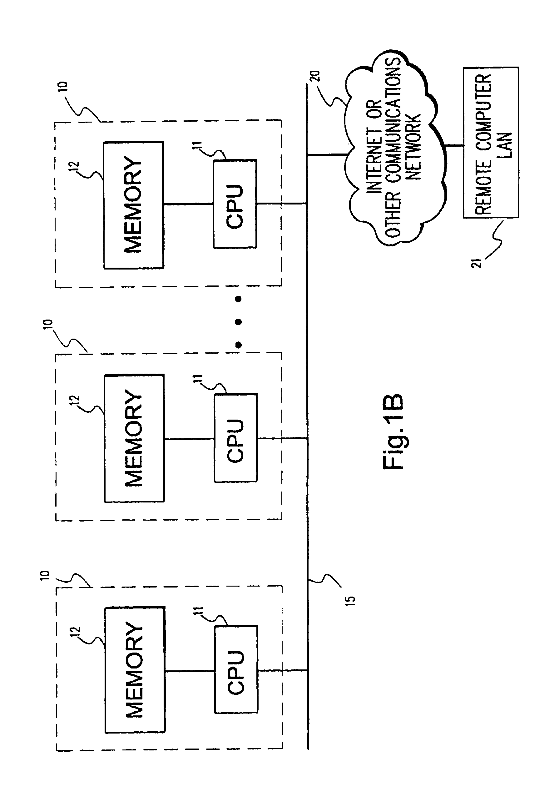
The following description is directed toward an exemplary embodiment for creating a response surface. The methodology for creating the response surface may be operative as an end-user application running, for example, under the Microsoffc Windows 95 / NT environment. However, creation of the response surface is not limited to any particular computer system or any particular environment. Instead, those skilled in the art will find that the system and methods presented herein may be advantageously applied to environments requiring management and / or optimization of any multiple control-variable critical industrial / scientific process or system, including chemical and mechanical process simulation systems, pressurized water reactor simulation systems, boiling wa...


PUM


Abstract

According to the method, a reactor core is shut down during the operation cycle. One or more fuel bundles of the reactor core are then moved to new positions within the reactor core to increase a total energy, output of the reactor core as compared to continuing operation of the reactor core without the shutting down and moving steps.

Description

BACKGROUND OF THE INVENTIONA Boiling Water Reactor (BWR) typically has a core formed of several hundred fuel bundle assemblies. Each fuel bundle assembly is formed of several fuel assembly rods, and each fuel assembly rod contains a variety of radioactive elements. Typically a number of different fuel bundle assemblies are created, and a core designer creates a core design using the different fuel bundle assemblies. The core design involves establishing the positioning of each bundle in the core, which is called the loading map, and establishing an operation plan over a period of time referred to as the operation or loading cycle. The operation plan establishes the operating parameters of the core over the loading cycle. Operating parameters (also referred to interchangeably herein as “independent control variables” and “design inputs”) include, for example, various physical component configurations and controllable operating conditions that may be individually adjusted or set (e.g....

Claims


Application Information

Patent Timeline
01 Mar 2005
Publication
US6862329B1
IPC
G21C19/20; G21C5/00; G21C5/02; G21C17/00; G21D3/00
CPC
G21C5/02; G21C19/205; G21D3/001; Y02E30/40; G21Y2002/201; G21Y2004/403; Y02E30/00; Y02E30/30
Inventors
KROPACZEK, DAVID JOSEPH; RUSSELL, II, WILLIAM EARL