
Method and apparatus for blanking T-waves from combipolar atrial cardiac signals based on expected T-wave locations

a combipolar atrial and cardiac signal technology, applied in bioelectric signal measurement, medical science, therapy, etc., can solve the problems of less reliable, significant far-field electrical signals detected, and high cost of bipolar leads, and achieve the effect of correct determination of the true atrial ra

Inactive Publication Date: 2005-03-01
PACESETTER INC
View PDF6 Cites 6 Cited by
  • Summary
  • Abstract
  • Description
  • Claims
  • Application Information

AI Technical Summary

Benefits of technology

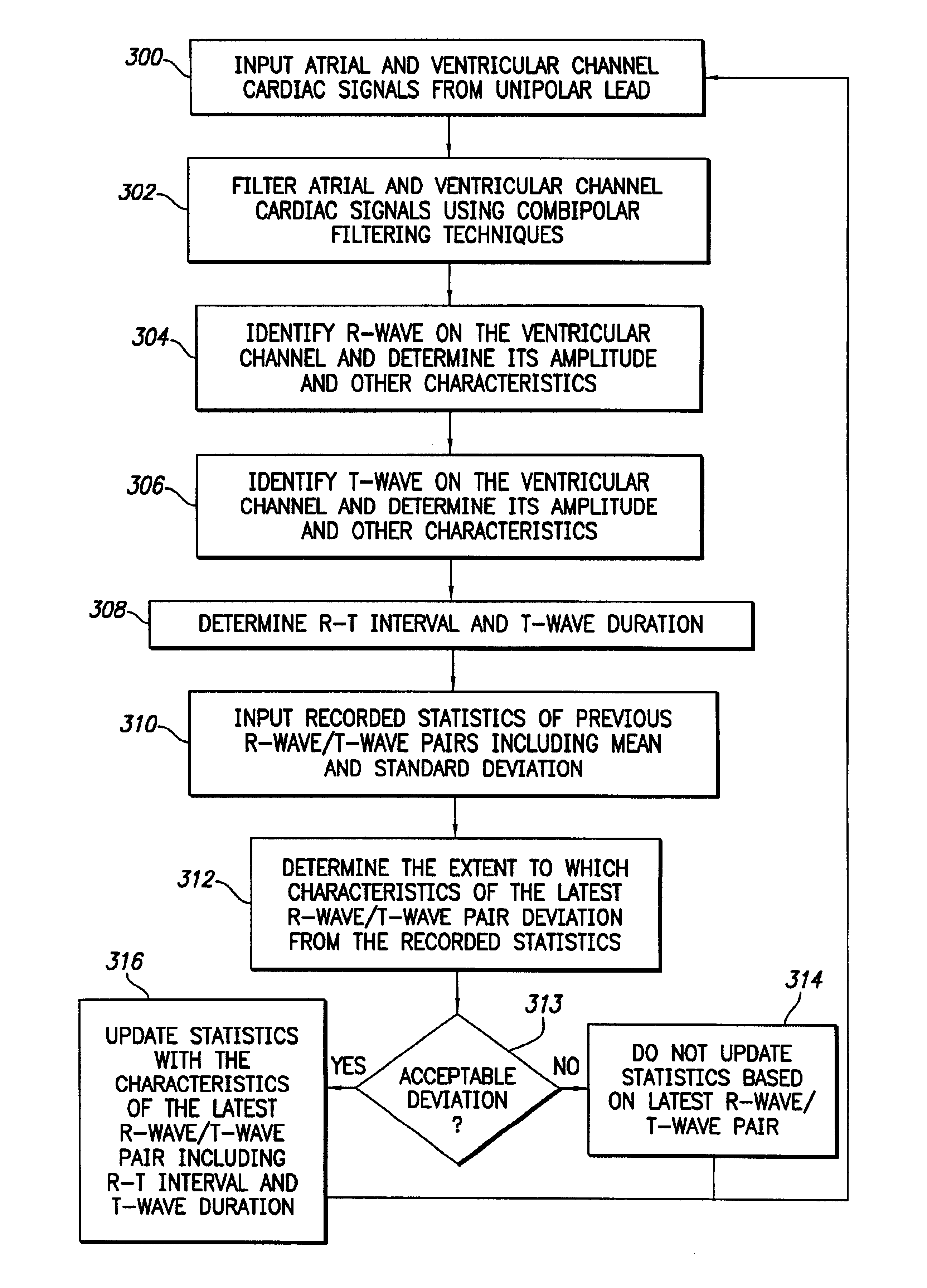
[0019]For example, the stimulation device can thereafter sense additional cardiac signals, identify R-waves in the additional cardiac signals, and apply stored averaged values of the R-T interval and the T-wave duration to identify expected locations and durations of the subsequent T-waves. Once the expected locations and durations of T-waves have been identified, the stimulation device blanks portions of an atrial channel of the additional cardiac signals to thereby ignore signals occurring within a period of time corresponding to the expected locations and durations of T-waves. By localizing the T-wave in this manner, then blanking it from the atrial channel from which the atrial rate is derived, a more correct determination of the true atrial rate can be obtained.
[0020]Preferably, statistical information representative of a large number of R-wave / T-wave pairs is generated and stored, including information pertaining to the minimum and maximum voltages of the R-waves and T-waves, the durations of the R-waves and T-waves, and the intervals between the R-waves and T-waves. Also, preferably, the statistical information includes averages and standard deviations for these values. Periodically, to accommodate possible changes in the R-T interval and T-wave duration, additional R-wave / T-wave pairs are analyzed by the stimulation device and the statistical information is adjusted accordingly. Also, preferably, before actually modifying the statistical information, a determination is made as to whether the characteristics of the newly detected R-wave / T-wave pairs deviate from the recorded average by no more than a predetermined amount, such as by no more than the first standard deviation. In this manner, the statistical information, from which the expected locations and durations of the T-waves are determined, is not improperly adjusted based upon anomalous R-wave / T-wave pairs, perhaps detected during flutter or fibrillation.

Problems solved by technology

A common problem with unipolar leads is that, because the device is sensing voltage differentials between the tip of the lead and the body of the device, significant far-field electrical signals are detected along with the intended atrial or ventricular cardiac signals.
However, bipolar leads are more expensive and are generally perceived as being less reliable than unipolar leads and hence are not preferred by all physicians.
One disadvantage, however, is that, because the atrial channel is detected based upon voltage differentials between the tips of the atrial and ventricular leads, ventricular signals are sensed as “near-field” signals.
Hence it may be difficult to filter the ventricular signals from the atrial channel.
Such may be particularly problematic when an combipolar electrode configuration is being used because, as noted, P-waves, R-waves, and T-waves may be sensed as being of the same order of magnitude on the atrial channel.
This problem exacerbated during an automatic mode switch (AMS), e.g., when switching the device from a DDD mode to a VVI or DDI mode.
However, such blanking schemes have proven less than satisfactory because P-waves may occur during the blanking intervals.
Hence, the device may significantly underestimate the true atrial rate, and thereby fail to detect the tachyarrhythmia, flutter or fibrillation occurring in the atria.
Thus, improper therapy may be administered.
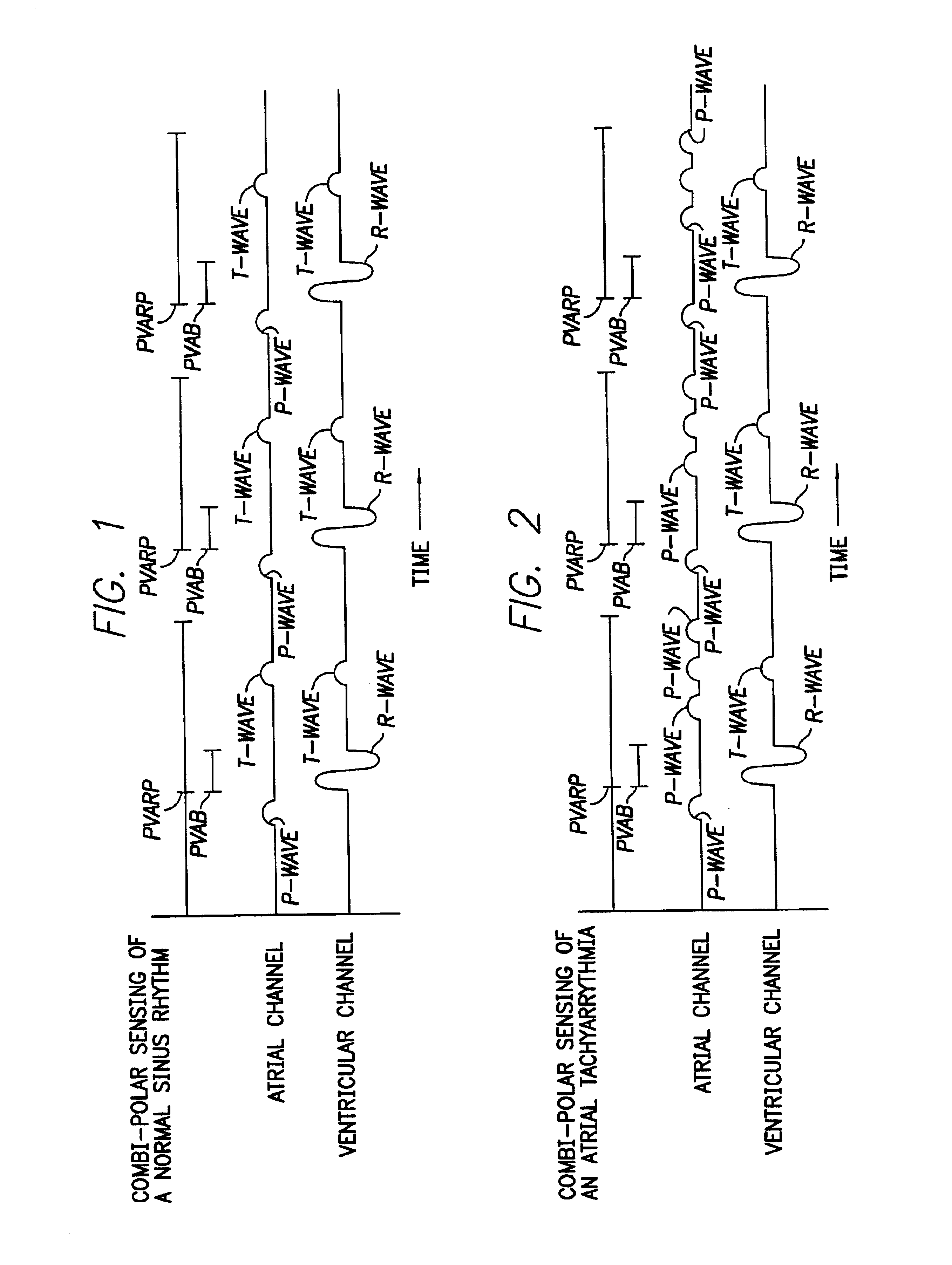
As a result, the atrial rate is substantially underestimated, possibly resulting in failure of the implantable device to administer appropriate anti-tachycardia pacing. FIG. 2 illustrates an extreme situation wherein a significant underestimation of the atrial rate can occur.
But even in more benign circumstances, occasional P-waves may be blanked by the PVARP interval resulting in a slight underestimation of the atrial rate, perhaps sufficient to trigger an unnecessary mode switching or the like.
However, T-waves may also be sensed during the PVARP interval resulting in an overestimation of the atrial rate, perhaps sufficient to trigger unnecessary anti-tachyarrhythmia therapy or at least sufficient to trigger an unnecessary mode switch.

Method used


Image

  • Method and apparatus for blanking T-waves from combipolar atrial cardiac signals based on expected T-wave locations
  • Method and apparatus for blanking T-waves from combipolar atrial cardiac signals based on expected T-wave locations
  • Method and apparatus for blanking T-waves from combipolar atrial cardiac signals based on expected T-wave locations

Examples


Embodiment Construction

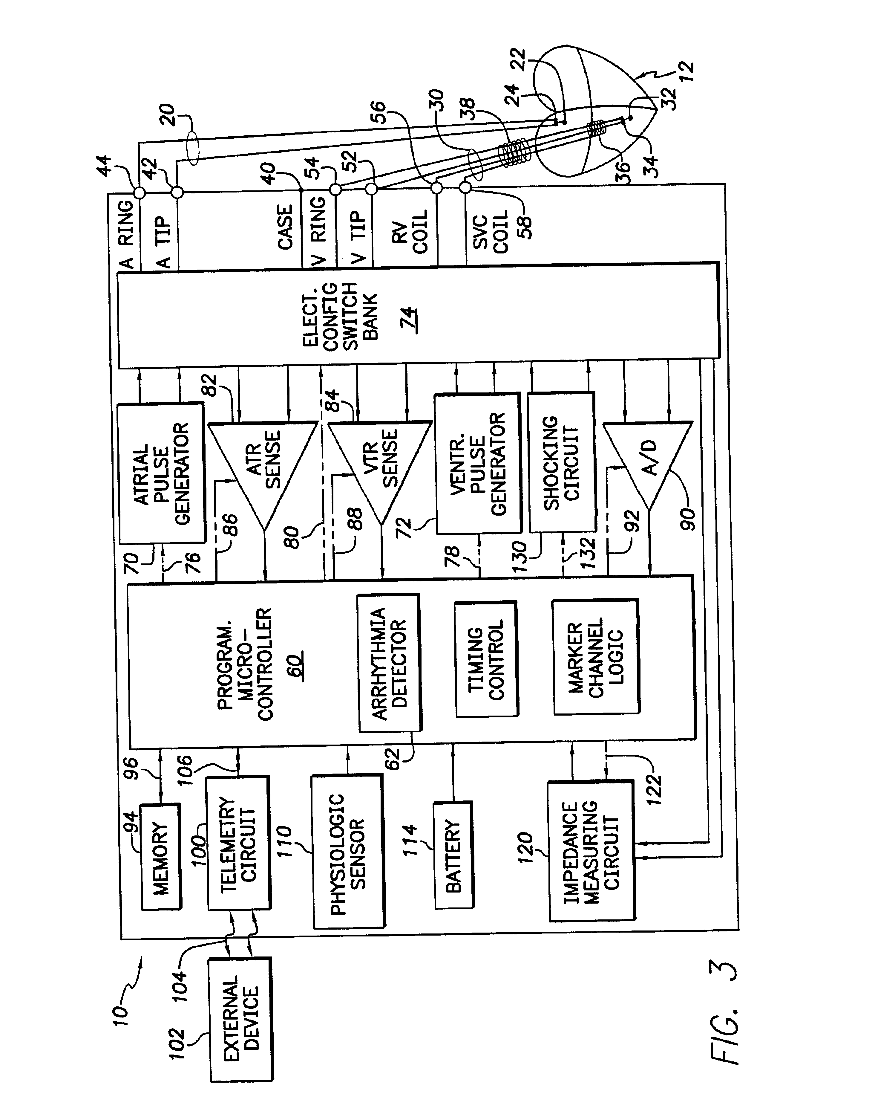
the system of FIG. 3 for blanking T-waves from an atrial channel cardiac signal based upon predetermined information identifying the location and duration of the T-wave relative to a preceding R-wave.

[0027]FIG. 5 is a graph illustrating exemplary atrial and ventricular channels of cardiac signals detected during a period of atrial tachyarrhythmia using combipolar sensing and specifically illustrating a T-wave blanking interval set to the expected location of T-waves within the cardiac signals.

[0028]FIG. 6 is a flow chart illustrating a method performed by the system of FIG. 3 for determining the expected location and duration of T-waves relative to R-waves for use by the method of FIG. 4.

[0029]FIG. 7 is a flow chart illustrating a state machine employed by a controller of the system of FIG. 3 for detecting R-waves, then blanking T-waves in accordance with the general method illustrated in FIG. 2.

DETAILED DESCRIPTION OF THE INVENTION

[0030]The following description is of the best mode...


PUM


Abstract

The stimulation device blanks T-waves from the atrial channel of an electrical cardiac signal by employing a T-wave blanking interval localized to the expected location and duration of the T-wave. To this end, the stimulation device determines the average interval between an R-wave and a T-wave in the patient in which the device is implanted and also determines the average duration of a T-waves within the patient. A T-wave blanking interval is initiated following the average R-T interval subsequent to detection of an R-wave and lasts for a period of time equal to the average T-wave duration. In this manner, highly localized T-wave blanking is achieved permitting P-waves or other atrial signals to be detected during remaining non-blanked portions of the atrial channel of the cardiac signal at least for the purposes of atrial rate detection. The relatively short T-wave blanking interval of the invention is particularly well suited for use in combipolar sensing systems. Method and apparatus implementations are described.

Description

CROSS-REFERENCE TO RELATED APPLICATIONS[0002]This application is related to commonly-assigned U.S. patent application Ser. No. 10 / 033,410, filed Oct. 25, 2001, titled METHOD AND APPARATUS FOR BLANKING T-WAVES FROM COMBIPOLAR ATRIAL CARDIAC SIGNALS BASED ON EXPECTED T-WAVE LOCATIONS, now issued as U.S. Pat. No. 6,711,438 B1.FIELD OF THE INVENTION[0003]The invention generally relates to implantable cardiac stimulation devices, such as pacemakers or implantable cardioverter-defibrillators (“ICDs”) and, in particular, to techniques for processing electrical cardiac signals detected using combipolar sensing.BACKGROUND OF THE INVENTION[0004]A pacemaker is a medical device, typically implanted within a patient, which recognizes various dysrhythmias such as an abnormally slow heart rate (bradycardia) or an abnormally fast heart rate (tachycardia) and delivers electrical pacing pulses to the heart in an effort to remedy the dysrhythmias. An ICD is a device, also implantable into a patient, w...

Claims


Application Information

Patent Timeline
Patent Type & Authority Patents(United States)
IPC IPC(8): A61B5/0452
CPCA61B5/0452A61B5/349A61B5/355
Inventor MCCLURE, KELLY H.FLORIO, JOSEPH J.BORNZIN, GENE A.
Owner PACESETTER INC
Learn More