Discrete jet atomizer

a technology of atomizer and discrete jet, which is applied in the direction of machines/engines, combustion types, lighting and heating apparatus, etc., can solve the problems of reducing spray control and narrow spray angle, affecting the combustion stability of combustion, and requiring a lot of development time to fine-tune the design geometry, etc., to achieve the effect of reducing noise, reducing carbon emissions, and improving ignition and combustion stability

Inactive Publication Date: 2005-03-08
DELAVAN
View PDF9 Cites 46 Cited by
  • Summary
  • Abstract
  • Description
  • Claims
  • Application Information

AI Technical Summary

Benefits of technology

The present invention may be an atomizer or air swirler which can provide favorable air streams, fuel sprays and fuel/air mixtures. In use, such as in gas turbine engine applications, the air swirlers and atomizers

Problems solved by technology

Air swirlers are often still designed by trial-and-error techniques, which involves much development effort and time to fine tune the design geometry or to achieve the desired spray characteristics.
Furthermore, the air streams emerging from the air swirler may overlap and cross each other in the vicinity of the air swirler, which results in energy loss, decreased spra

Method used


Image

  • Discrete jet atomizer
  • Discrete jet atomizer
  • Discrete jet atomizer

Examples


Embodiment Construction

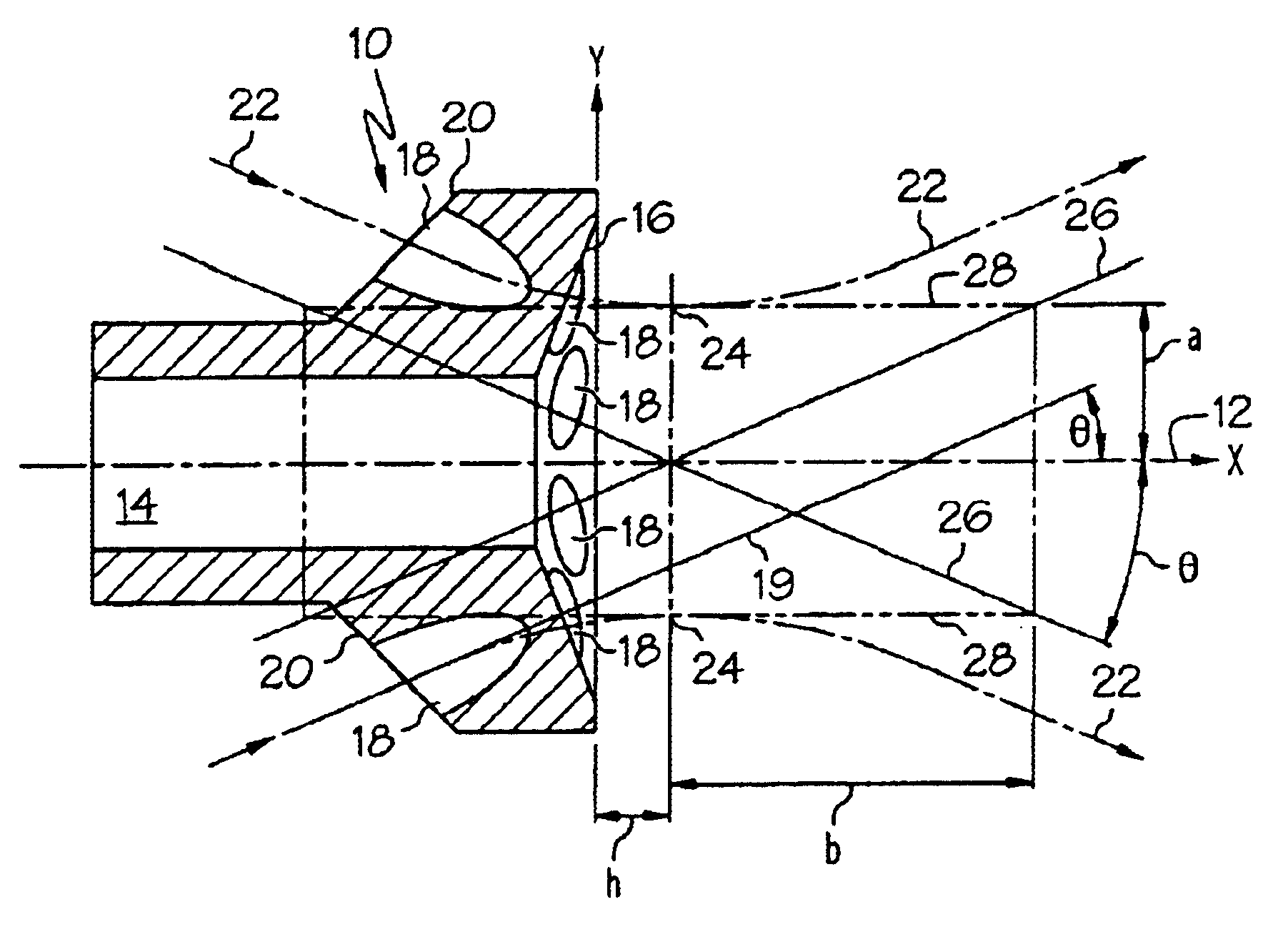
FIG. 1 illustrates an air swirler 10 and a coordinate system and design parameters for determining the patterns of the air streams passing therethrough. The air swirler 10 of FIG. 1 includes a central axis 12 (the x axis of FIG. 1) and an axially-extending opening 14 centered about the central axis 12. The air swirler 10 includes a front face 16 and a set of radially spaced openings 18 extending from a back surface 20 of the air swirler 10 to the front face 16 thereof. Each of the openings 18 may have a generally circular cross section and a central axis 19. However, the openings 18 may have different shapes besides circular, such as an “airfoil” or quadrilateral shape.

Each of the openings 18 is spaced apart from the central axis 12 of the air swirler 10 at the front face 16 by a radial offset distance a. The central axis 19 of each of the openings 18 may form an angle with the central axis 12 of the air swirler 10 by an angle designated the angular offset θ, which may be an acute a...


PUM


Abstract

An atomizer including a fuel output portion shaped to provide a fuel output and an air swirler portion shaped to direct streams of air at the fuel. The air swirler portion includes an outer opening and an inner opening located radially inwardly relative to the outer opening. The inner and outer openings are arranged such that an air stream passed through the inner opening does not intersect a conical section defined by an air stream passed through the outer opening unless both of said air streams are moving at least partially radially outwardly.

Description

The present invention is directed to an atomizer, and more particularly, to an atomizer for creating a liquid / gas spray.BACKGROUNDLiquid atomizers are widely used in industrial, agricultural, propulsion and other systems. Such liquid atomizers are typically used to produce a spray (i.e., a liquid / gas mixture including fine droplets of the liquid) for various purposes, such as creating a spectrum of droplets, control or metering of liquid throughput, dispersion of liquid droplets for mixing with surrounding air, and generation of droplet velocity or penetration. In one embodiment, the transformation of bulk liquids to sprays can be achieved, for example, by directing various forms of energy, such as hydraulic, pneumatic, electrical, acoustical, or mechanical energy, to the bulk liquid to cause the liquid to break up into droplets.Pneumatic atomizers are often used in gas turbine engine applications. Most pneumatic atomizers used in gas turbine engine applications include an atomizer ...

Claims


Application Information

Patent Timeline
IPC IPC(8): F23D11/10B05B7/08B05B7/10F23R3/12F23R3/28
CPCB05B7/08B05B7/10F23D11/108F23R3/28F23R3/12F23D2210/00F23D2206/10
Inventor MAO, CHIEN-PEISHORT, JOHN EARL
Owner DELAVAN
Why Eureka
Try Eureka