Balloon pump system having a pressure reservoir muffler

a balloon pump and reservoir technology, applied in the direction of heart stimulators, prostheses, therapy, etc., can solve the problems of unfavorable “rushing” sound, unaware of any prior incorporation of honeycombs,

Inactive Publication Date: 2005-03-08
DATASCOPE
View PDF6 Cites 9 Cited by
  • Summary
  • Abstract
  • Description
  • Claims
  • Application Information

AI Technical Summary

Problems solved by technology

Although the prior art system described above permits rapid inflation and deflation cycles, the configuration of this system, specifically the burst of air flow into vacuum reservoir 32 upon the activation of the solenoid valve 34, creates an undesirable “rushing” sound.
Various devices for directing a

Method used


Image

  • Balloon pump system having a pressure reservoir muffler
  • Balloon pump system having a pressure reservoir muffler
  • Balloon pump system having a pressure reservoir muffler

Examples


Embodiment Construction

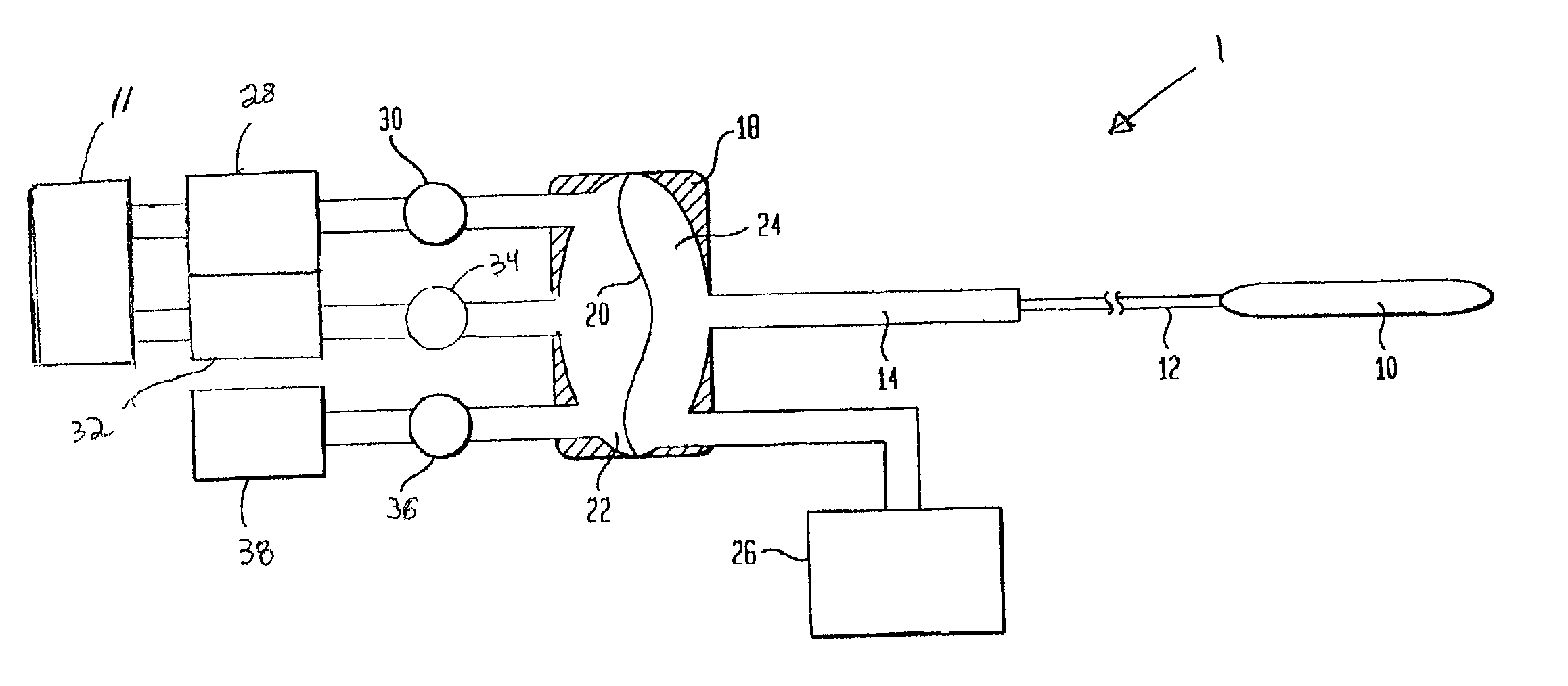
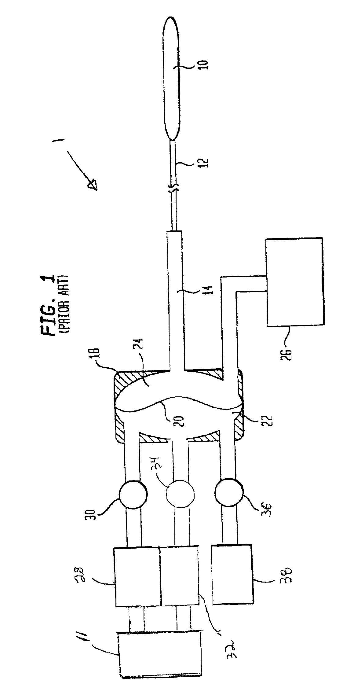
FIG. 1 illustrates a prior art intra-aortic balloon system 1 comprising an intra-aortic balloon catheter 12, an extender 14 connecting said intra-aortic balloon catheter 12 to an isolator 18, a gas source 26, a compressor 11, a vent 38, and a positive pressure reservoir 28 and negative pressure reservoir 32 connected in parallel between compressor 11 and isolator 18. Intra-aortic balloon catheter terminates in a balloon 10. Isolator 18 comprises an enclosed volume divided by a pliant membrane 20 into a primary side 22 and a secondary side 24. The entire volume between membrane 20 and balloon 10 is typically filled with a gas, such as helium, supplied by gas source 26. Positive pressure reservoir 28 is connected through a solenoid valve 30 to the input or primary side 22 of isolator 18. Similarly, negative pressure reservoir 32 is connected through a solenoid valve 34 to the input or primary side 22 of isolator 18. Both positive pressure reservoir 28 and negative pressure reservoir 3...


PUM


Abstract

A vacuum reservoir, for use with an intra-aortic balloon pump or other system, containing a muffling means having a honeycomb-like cell structure or other flow straightening structure.

Description

BACKGROUND OF THE INVENTION1. Field of the InventionThe invention relates to an enhanced quieter intra-aortic balloon pump system. More particularly, the invention relates to a muffling device for a vacuum pressure reservoir commonly used in intra-aortic balloon pump systems.2. Description of the Prior ArtIntra-aortic balloon pump therapy is frequently prescribed for patients who have suffered a heart attack or some other form of heart failure. In such therapy, a thin balloon is inserted through an artery into the patient's aorta. The balloon is connected through a series of thin tubes to a complex apparatus which causes the balloon to inflate and deflate repeatedly in time with the patient's heart beat, thereby assuming some of the load of the heart during the patient's recovery period.The inflation / deflation apparatus supplies positive pressure for expanding the balloon during an inflation cycle and negativepressure for contracting the balloon during a deflation cycle. In a conven...

Claims


Application Information

Patent Timeline
IPC IPC(8): A61M1/10A61M60/139A61M60/295A61M60/497
CPCA61M1/1072A61M1/1062A61M2205/42A61M60/43A61M60/274A61M60/497A61M60/139A61M60/295
Inventor WILLIAMS, JONATHANHOFF, ROBERTKAUSHANSKY, YEFIM
Owner DATASCOPE
Why Eureka
Try Eureka