Method and apparatus for producing synthesis gas from carbonaceous materials

a technology of carbonaceous materials and synthesis gas, which is applied in the direction of indirect heat exchangers, combustible gas production, lighting and heating apparatus, etc., can solve the problems of large ash production, pyrolysis reaction with several undesired, and further generation of slag, so as to improve the purity of the formed gas and carefully control the reaction temperature

Inactive Publication Date: 2005-03-08
JBK EXTRACTIONS
View PDF11 Cites 209 Cited by
  • Summary
  • Abstract
  • Description
  • Claims
  • Application Information

AI Technical Summary

Problems solved by technology

Unfortunately, the pyrolysis reaction has several undesired results.
Further, it produces large amounts of ash and further creates slag.
Slag is unusable and must be disposed.

Method used


Image

  • Method and apparatus for producing synthesis gas from carbonaceous materials
  • Method and apparatus for producing synthesis gas from carbonaceous materials

Examples


Embodiment Construction

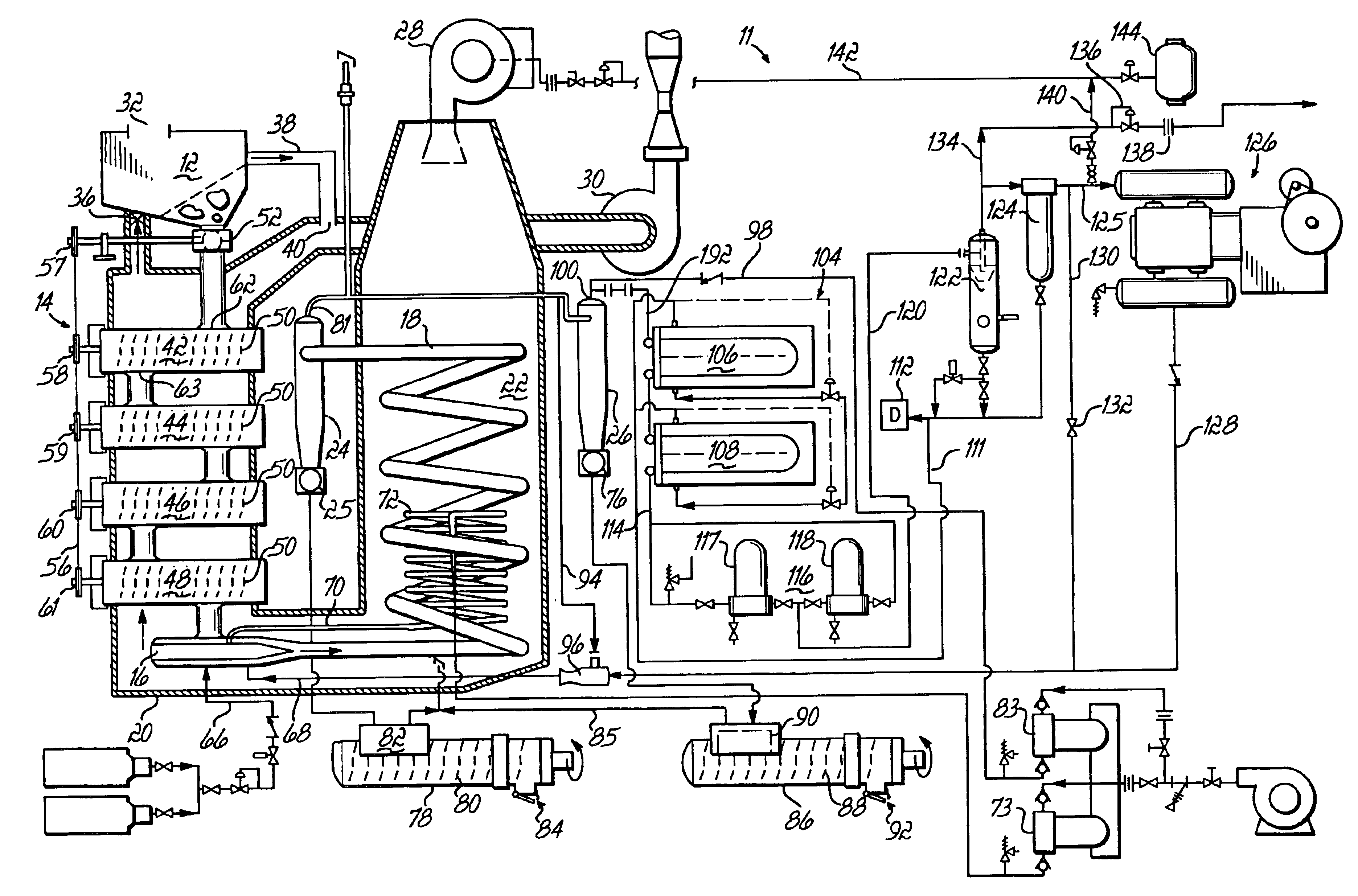
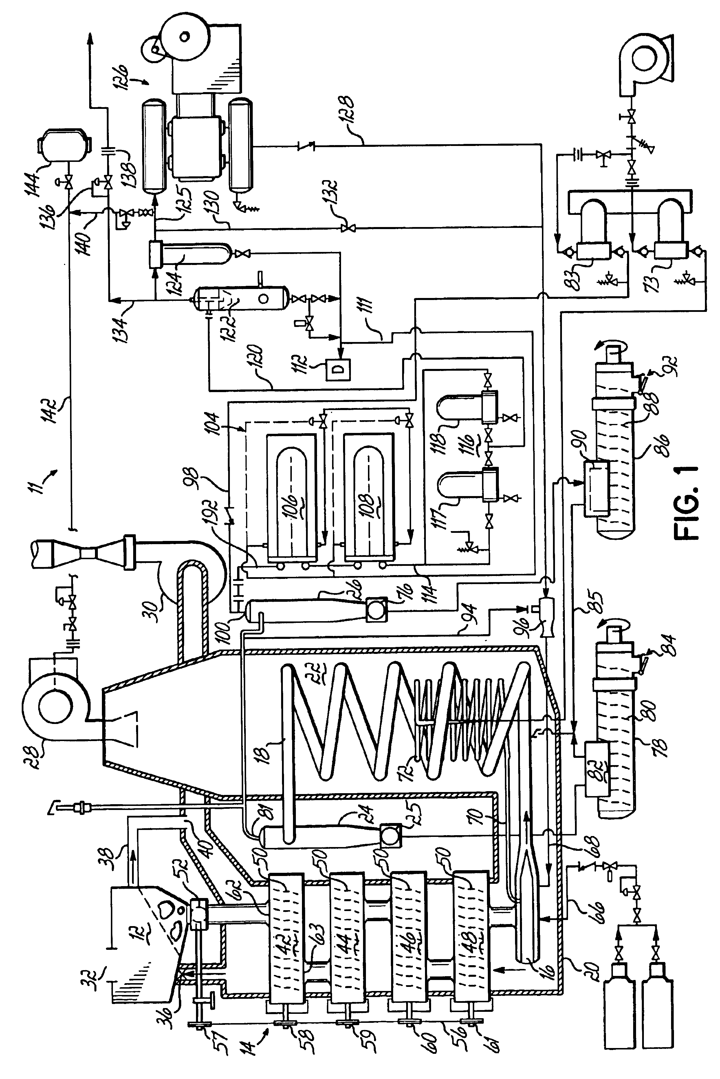
As shown in the drawing, the reactor 11 used in the present invention includes a feed hopper 12 which introduces material into a devolatilization section 14. The material from the devolatilization section 14 is directed to a cyclone feeder 16, which adds steam and directs this through coils 18 that are located in a burner section 22 of furnace 20. The heated coils 18 lead to first and then second cyclone separators 24,26 which separate gas from ash. The ash is collected for further use.

As shown in the drawings, the devolatilization section 14 is also located in furnace 20 downstream of burner section 22. A forced draft burner 28 is used to heat the burner section 22. The exhaust gases are then directed through the furnace 20 and around the devolatilization section 14 and pulled from the unit by an induced draft blower 30.

The feed hopper 12 is sealed and includes an inlet section 32 and a delumper (not shown). Gas is introduced from the furnace section 22 through valve 36 to reduce m...


PUM

PropertyMeasurementUnit
temperaturesaaaaaaaaaa
temperatureaaaaaaaaaa

Abstract

A method of producing syn gas from biomass or other carbonaceous material utilizes a controlled devolatilization reaction in which the temperature of the feed material is maintained at less than 450° F. until most available oxygen is consumed. This minimizes pyrolysis of the feed material. The method and apparatus utilizes the formed synthesis gas to provide the energy for the necessary gasification. This provides for a high purity syn gas and avoids production of slag.

Description

BACKGROUND OF THE INVENTIONCarbonaceous feed material such as coal, wood chips and other biomass, and the like, have been used to produce synthesis gas which is carbon monoxide and hydrogen. The syn gas reaction is a redox reaction in which steam is combined with carbon at elevated temperatures to produce carbon monoxide and hydrogen. The reaction generally occurs at greater than 1000° F. Generally, the carbonaceous starting material includes oxygen which at elevated temperatures, i.e., greater than 450° F., will react with the carbon and pyrolysis will occur. This is an exothermic reaction. Most syn gas production has utilized the heat generated in this portion of the reaction to fuel the subsequent gasification.Unfortunately, the pyrolysis reaction has several undesired results. Primarily it produces carbon dioxide which must be removed. Further, it produces large amounts of ash and further creates slag. Basically, it raises the temperature of the feed material to above the meltin...

Claims


Application Information

Patent Timeline
Patent Type & Authority Patents(United States)
IPC IPC(8): C10J3/46C10J3/00C10J3/48C10J3/54C10J3/66C10J3/50
CPCC10J3/466C10J3/506C10J3/54C10J3/66C10J3/80C10J3/485C10J2300/1892C10J2200/15C10J2200/158C10J2300/0909C10J2300/0916C10J2300/092C10J2300/093C10J2300/0973C10J2300/1223C10J2300/1634C10J2300/1671C10J2300/1687C10J2300/1823C10J2300/1876C10J2300/1884C10J2300/1215C10J2300/1246Y02P20/145
Inventor KLEPPER, ROBERT E.
Owner JBK EXTRACTIONS
Why Eureka
Try Eureka