Method of detecting wear on a substrate using a fluorescent indicator

a fluorescent indicator and substrate technology, applied in the direction of fluorescence/phosphorescence, optical radiation measurement, instruments, etc., can solve the problems of difficult to determine the point at which the coating becomes worn, the coating begins to wear to a point at which the coating no longer provides the intended function, and the surface coverage is not complete, etc., to achieve the effect of easy and fast determination and convenient operation

Inactive Publication Date: 2005-03-08
3M INNOVATIVE PROPERTIES CO
View PDF19 Cites 53 Cited by
  • Summary
  • Abstract
  • Description
  • Claims
  • Application Information

AI Technical Summary

Benefits of technology

In some embodiments, the method further includes coating a second composition on the coated surface prior to exposing the coated surface to wear. In another embodiment, the method further includes coating a first layer and a second layer on the coated substrate after coating the substrate with the composition that includes a fluorescent compound. In other embodiments, the step of coating includes coating a portion of the substrate surface with the composition that includes a fluorescent compound. In one embodiment, the method further includes coating a first portion of the substrate surface with the composition that includes a fluorescent compound and coating a second portion of the substrate with a second composition, the second composition being essentially free of the fluorescent compound.
The invention features a method by which the presence or absence of a coating on a substrate surface can be easily and quickly determined through visual observation. A handheld ultraviolet light source such as a black light can be used to radiate the surface. The method is non-destructive and easy to perform.
The method includes employing a fluorescent indicator that, when properly selected, can be used without altering the look or aesthetics of the coating.

Problems solved by technology

Because these coatings and finishes are often clear and colorless, it can be difficult to determine whether the surface coverage is complete.
As the surface is used, for example, contact with pedestrian traffic in the case of floors, the coating begins to wear to a point at which the coating is no longer providing its intended function.
It is often difficult to determine the point at which the coating becomes worn to such an extent that the surface should be refinished.

Method used


Image

  • Method of detecting wear on a substrate using a fluorescent indicator
  • Method of detecting wear on a substrate using a fluorescent indicator
  • Method of detecting wear on a substrate using a fluorescent indicator

Examples


example 1

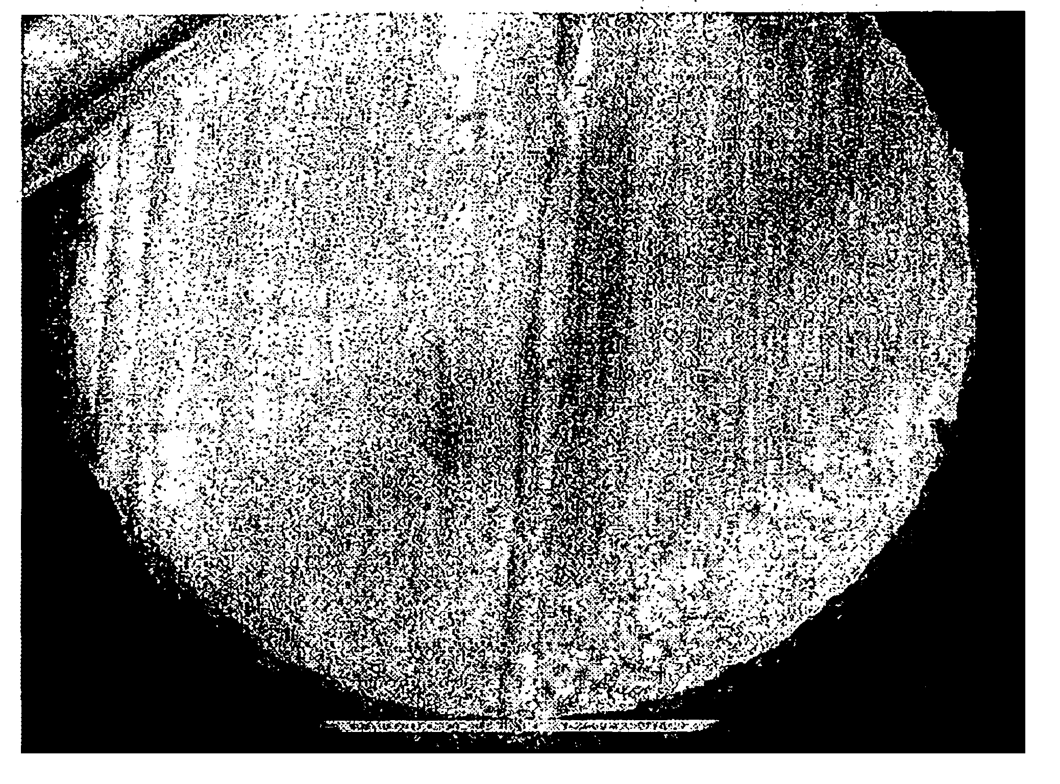
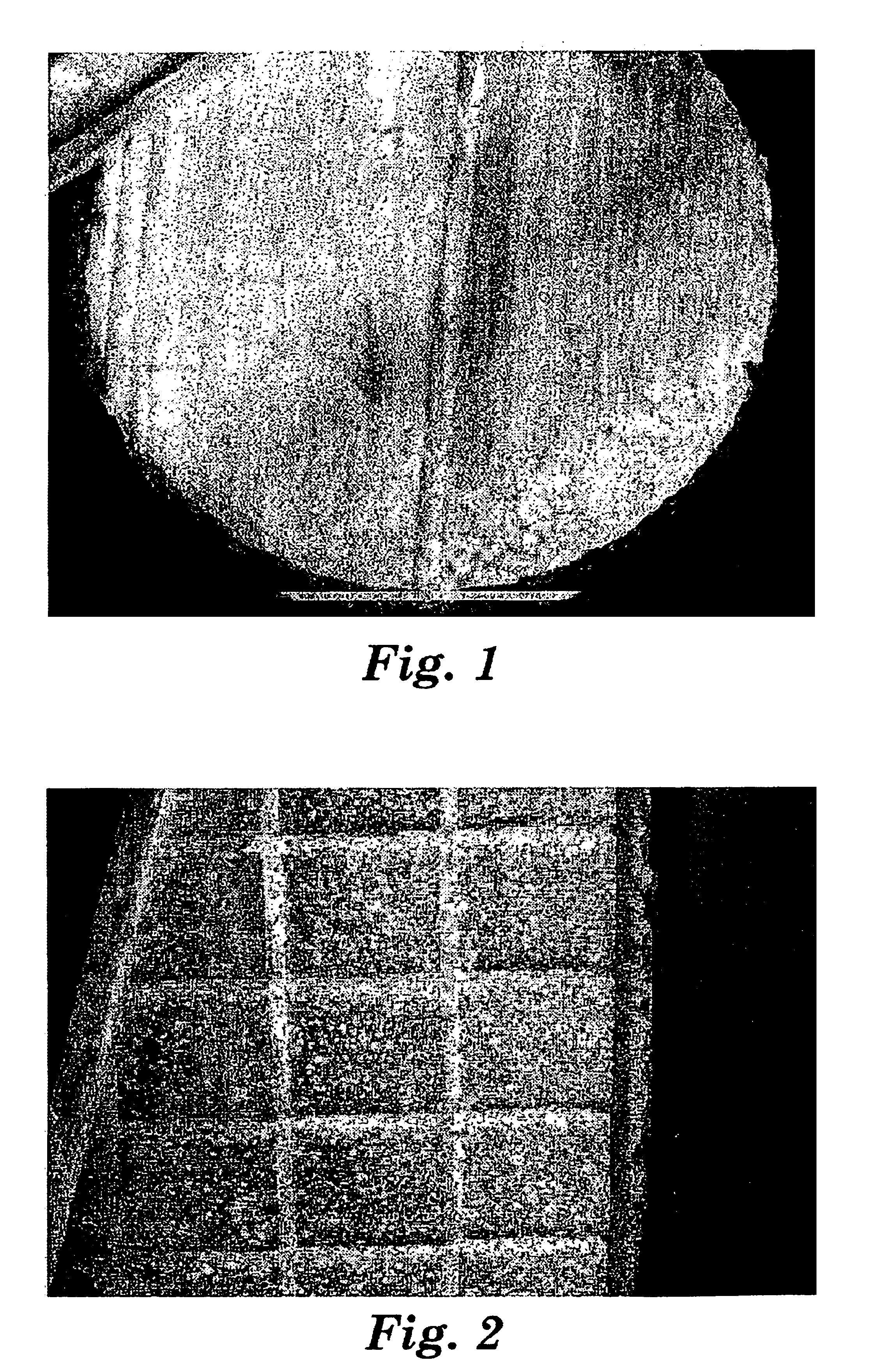
A fluorescent indicator mildew prevention composition was prepared by combining 0.0005% ECCOWHITE fluorescent dye (Eastern Color and Chemical Co., Greenville, S.C.) and SCOTCHGARD Mildew Shield mildew preventer solution (Minnesota Mining and Manufacturing Company, St. Paul, Minn.). The composition was applied on plasterboard, wood, grout and ceramic. The treated surfaces were exposed to mercury black light. The coating and defects therein were visible under the black light. The plasterboard results, radiated with black light, are depicted in the photograph in FIG. 1.

example 2

A grout and tile protector composition including fluorescent indicator was prepared by adding 0.0002% ECCOWHITE fluorescent dye to SCOTCHGARD grout protector aqueous solution (Minnesota Mining and Manufacturing Company). The composition was applied on ceramic tiles and grout. The treated surfaces were exposed to mercury black light. The coating and defects therein were visible under the black light. The results, radiated with black light, are depicted in the photograph in FIG. 2.

example 3

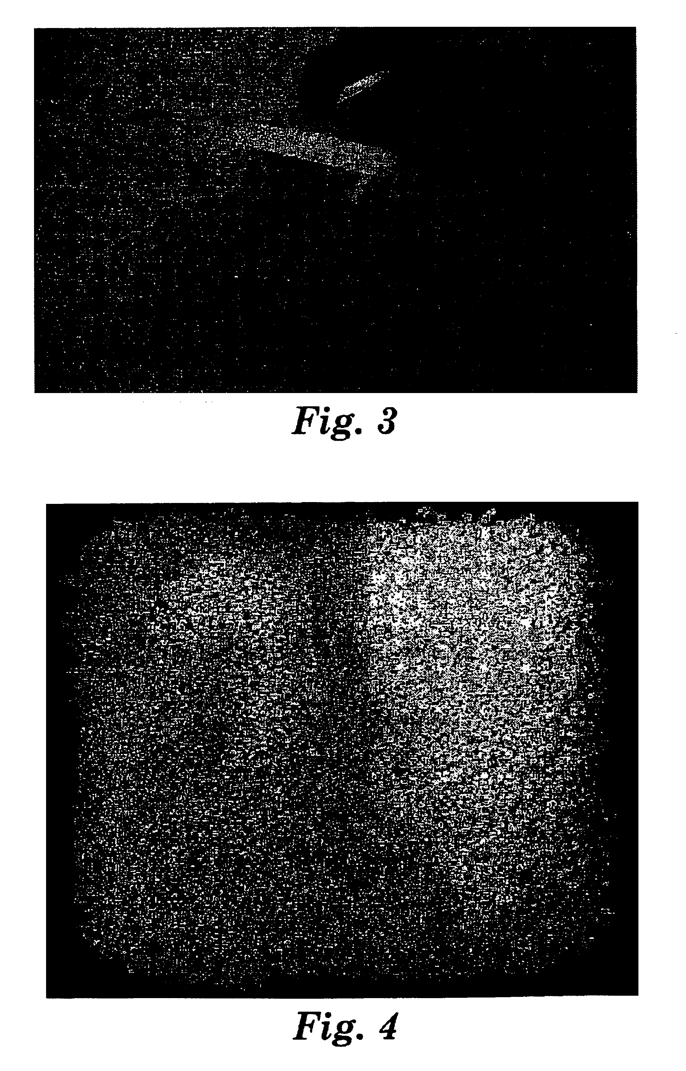
A floor finish coating was prepared by adding 0.0002% ECCOWHITE fluorescent dye to SPANGLE floor finishing composition (Minnesota Mining and Manufacturing Company). Three layers of the floor finishing composition were coated on the floor. Two floor tiles in a high traffic area were coated with two inches of the fluorescent dye-containing floor finishing composition. The treated floor was allowed to dry completely and two more layers were applied on top of the first layer. The first layer, that is, marker layer, was clearly seen when radiated with black light. The results, radiated with black light, are depicted in the photograph in FIG. 3.


PUM

PropertyMeasurementUnit
wavelengthaaaaaaaaaa
fluorescentaaaaaaaaaa

Abstract

A method of detecting wear on a substrate including coating a composition that includes a fluorescent compound on the surface of a first substrate, exposing the coated surface to wear, exposing the coated surface to radiation capable of exciting the fluorescent compound, and detecting the presence or absence of fluorescence.

Description

BACKGROUND OF THE INVENTIONThe invention relates to detecting wear on a coated substrate.Coatings and finishes are often applied to floors, walls and counter tops to improve durability, alter aesthetics, decrease maintenance requirements, prevent microorganism growth, and impart water resistance and chemical resistance to the surface. The coatings and finishes are often applied in several coating applications to obtain a finish having the desired appearance and durability. Because these coatings and finishes are often clear and colorless, it can be difficult to determine whether the surface coverage is complete.As the surface is used, for example, contact with pedestrian traffic in the case of floors, the coating begins to wear to a point at which the coating is no longer providing its intended function. It is often difficult to determine the point at which the coating becomes worn to such an extent that the surface should be refinished. It would be helpful to be able to easily dete...

Claims


Application Information

Patent Timeline
Patent Type & Authority Patents(United States)
IPC IPC(8): G01N3/56G01N21/84G01N3/00G01N3/06G01N21/64G01N21/88G01N21/91
CPCG01N3/56G01N21/8422G01N21/64G01N2203/0652G01N21/91C09D5/32C09D5/00C09D7/41C08K5/0041C09K11/06
Inventor CHEN, YEN LANEWILLIAMSON, GARY S.
Owner 3M INNOVATIVE PROPERTIES CO
Why Eureka
Try Eureka