Process for anticipating the service life of a rare gas discharge lamp and a system for anticipating the service life of rare gas discharge lamp

a technology for rare gas discharge lamps and service life, which is applied in the field of process the system for anticipating the service life of rare gas discharge lamps. it can solve the problems of flickering in the light, difficult to see the images, and flickering in the image, so as to achieve the effect of reliably anticipating the service li

Inactive Publication Date: 2005-03-08
USHIO DENKI KK
View PDF4 Cites 16 Cited by
  • Summary
  • Abstract
  • Description
  • Claims
  • Application Information

AI Technical Summary

Benefits of technology

The invention was devised to eliminate the above described disadvantages in the prior art. Thus, a primary object of the present invention is to devise a new process which will reliably anticipate the service life of a rare gas discharge lamp. Furthermore, a parallel object of the invention is to develop a system for carrying out the process. That is, the object of the invention is to devise a new process for anticipating the service life of a rare gas discharge lamp in which, by determining the voltage which is an electrical property of ...

Problems solved by technology

In these rare gas discharge lamps, as was described above, there was the disadvantage that flickering forms in the images and it becomes difficult to see the images if, for example, in the case of use as a light source of a projection device, the flicker phenomenon occurs.
Furthermore, in these rare gas discharge lamps, there was the disadvantage that flickering occurs in the light which has passed through the liquid crystals and which has been projected on the test screen, and that it can no longer be correctly assessed in what area the liquid crystals are disrupted if, for example, in the case of use as a light source of a device for testing a liquid crystal cell, the flicker phenomenon oc...

Method used


Image

  • Process for anticipating the service life of a rare gas discharge lamp and a system for anticipating the service life of rare gas discharge lamp
  • Process for anticipating the service life of a rare gas discharge lamp and a system for anticipating the service life of rare gas discharge lamp
  • Process for anticipating the service life of a rare gas discharge lamp and a system for anticipating the service life of rare gas discharge lamp

Examples


Embodiment Construction

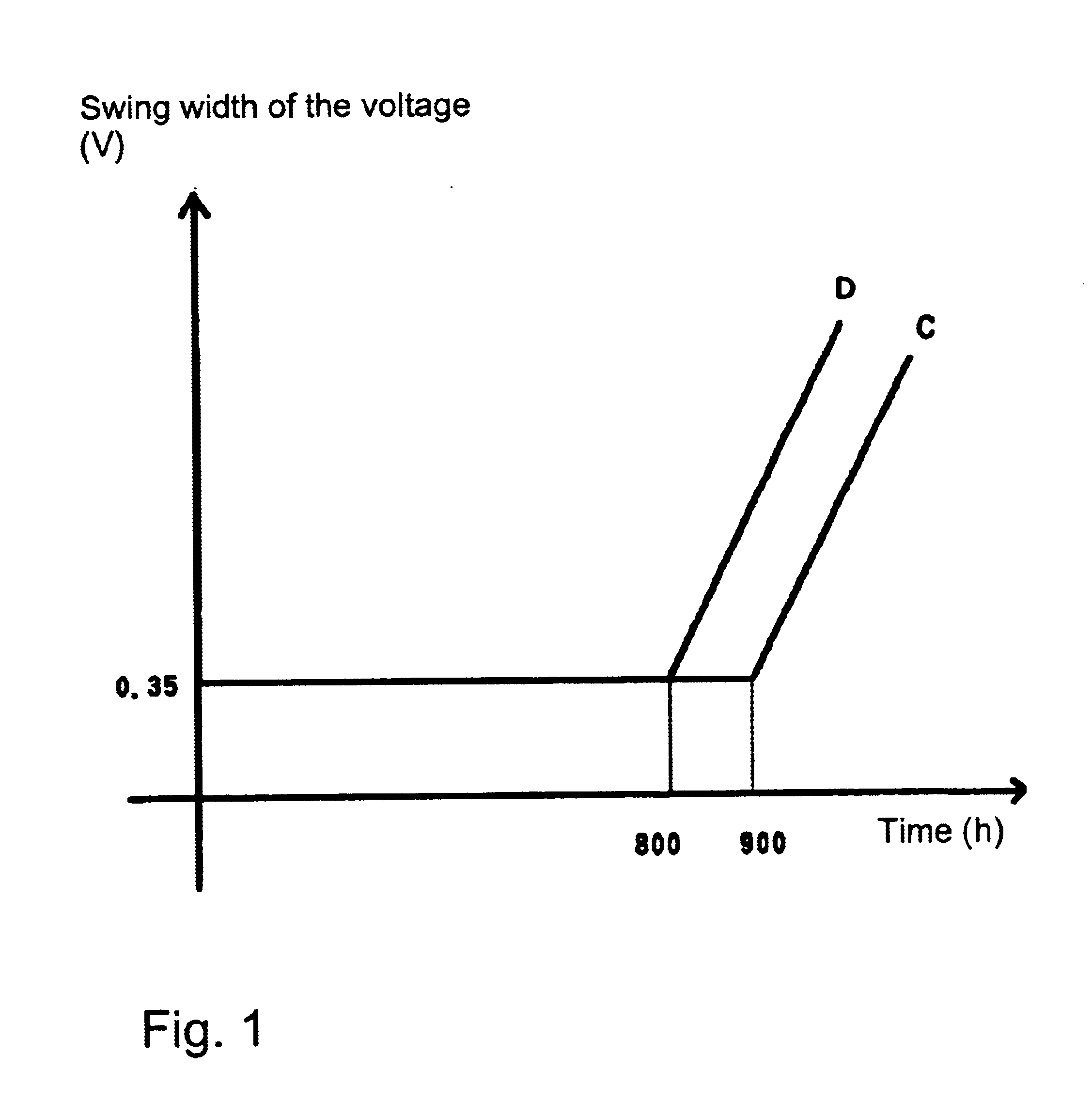
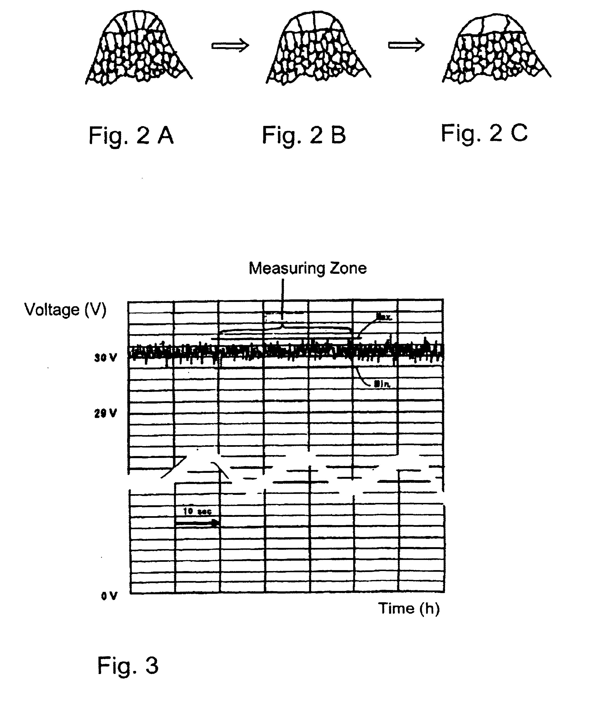
The process in accordance with the invention for anticipating the lifetime is described below using one embodiment, the lamps 1 and 2 according to FIG. 4 being taken as the example. These lamps are operated with a rated current of 80 A. The value of the swing width of the voltage (magnitude of the voltage fluctuation as indicated above) during operation with the rated current of 80 A is shown using the graphic A of the lamp 1 and the plot B of the lamp 2. Furthermore, the value of the swing width of the voltage during operation with a rated current which has been reduced to 40 A is shown using the graphic a for the lamp 1 and the plot b for the lamp 2. The lifetime of these lamps before occurrence of the flicker phenomenon is defined by the time at which the value of the swing width of the voltage at the rated current exceeds 0.35 V. In the lamp 1, the time of the service life of the lamp before occurrence of flicker is roughly 1000 hours, while 50 hours before, specifically at 950 ...


PUM


Abstract

The rare gas discharge lamp is supplied with a current, which is lower than the rated current, the voltage of the rare gas discharge lamp is determined at this instant and the swing width of this voltage is measured. A comparator for comparing measured values of the swing width of the voltage of the rare gas discharge lamp when the current control supplies a reduced current, which is lower than the rated current. A service life converter for converting the difference value output by the comparison means into an indication of the service life of the rare gas discharge lamp.

Description

BACKGROUND OF THE INVENTION1. Field of the InventionThe invention relates to a process for anticipating the service life of a rare gas discharge lamp and a system for anticipating the service life of a rare gas discharge lamp. The invention relates especially to a process for anticipating the service life of a rare gas discharge lamp which is a discharge lamp of the short arc type used as the light source of a projection device, a device for inspection of a liquid crystal cell or the like, a film or the like being irradiated with light and images being projected using this light. The invention furthermore relates to a system for anticipating the service life of a rare gas discharge lamp. The invention is useful, for example, in technical areas, such as in the above described projection device (projector), a device for inspection of a liquid crystal cell, stage illumination, a surgical lamp, an endoscope, a spotlight and the like as a new process for anticipating the service life of ...

Claims


Application Information

Patent Timeline
IPC IPC(8): H05B41/292H05B37/00H05B37/03H05B41/28H01J9/44
CPCH05B37/03H05B41/2925Y02B20/208H05B47/20Y02B20/00
Inventor OTSUKA, MASAHARUMATSUSHIMA, TAKEO
Owner USHIO DENKI KK
Why Eureka
Try Eureka