Method and apparatus for creating an EH antenna

a technology of eh antenna and cross-field antenna, which is applied in the field of radio frequency communication, can solve the problems of complicated physical structure, large space required for typical wire antennas, and limited distance between readers and transponders

Inactive Publication Date: 2005-03-08
EH ANTENNA SYST
View PDF5 Cites 95 Cited by
  • Summary
  • Abstract
  • Description
  • Claims
  • Application Information

AI Technical Summary

Benefits of technology

The disadvantages of the prior art are overcome by the present invention which, in one aspect is an antenna system for transmitting and receiving, in association with a radio device, that develops an H-field and an E-field corresponding to a radio frequency power signal having a voltage and a current, the voltage having a phase relationship to the current. The antenna system includes a Hertz-type radiating element. A phasing and matching circu...

Problems solved by technology

Thus, the typical wire antenna requires a substantial amount of space as a function of the wavelength being transmitted and received.
The Crossed Field Antenna has the disadvantage of requiring a complicated physical structure to develop the E and H fields in separate sections of the antenna.
However, with tradi...

Method used


Image

  • Method and apparatus for creating an EH antenna
  • Method and apparatus for creating an EH antenna
  • Method and apparatus for creating an EH antenna

Examples


Embodiment Construction

A preferred embodiment of the invention is now described in detail. Referring to the drawings, like numbers indicate like parts throughout the views. As used in the description herein and throughout the claims, the following terms take the meanings explicitly associated herein, unless the context clearly dictates otherwise: the meaning of “a,”“an,” and “the” includes plural reference, the meaning of “in” includes “in” and “on.”

A general discussion of Poynting vector theory may be found in the disclosure of U.S. Pat. Nos. 5,155,495 and 6,025,813, which are incorporated herein by reference.

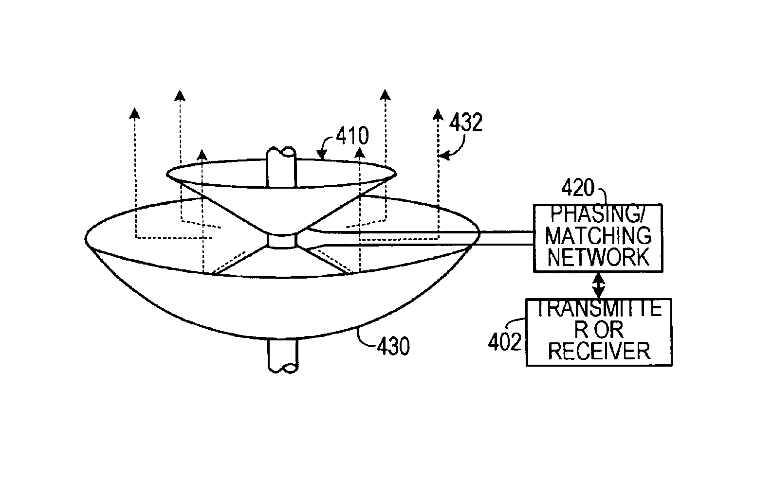
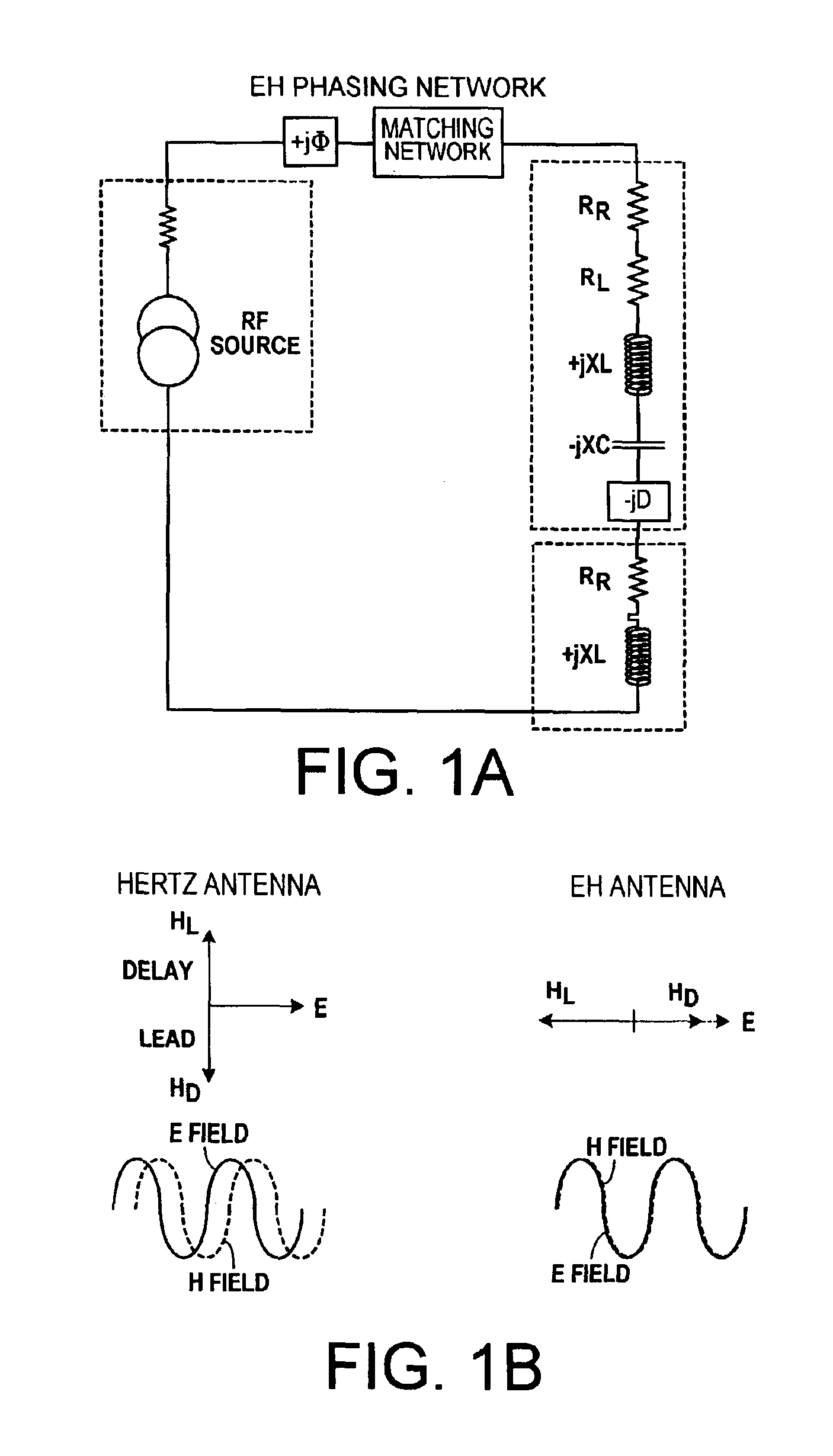
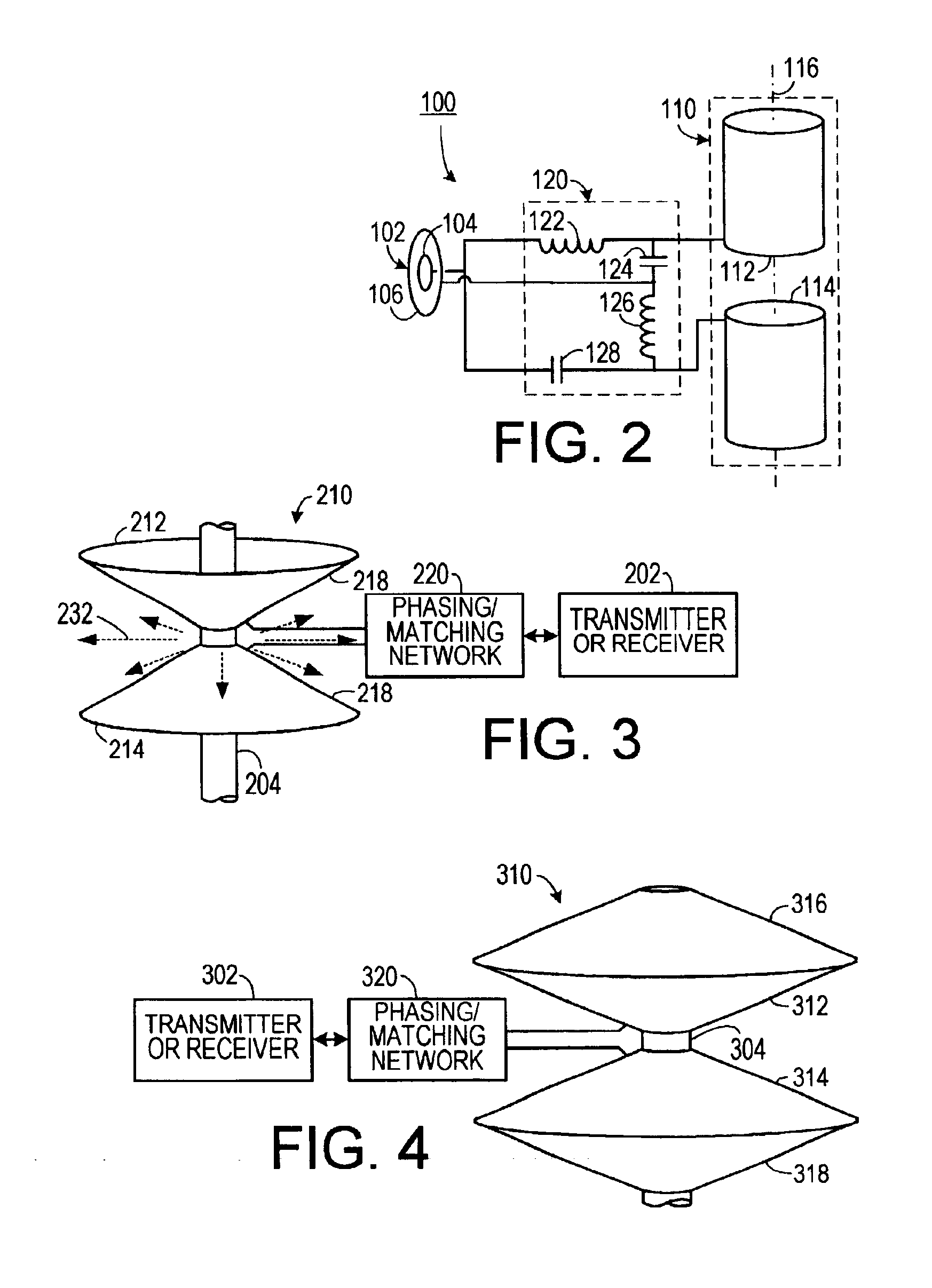
The EH Antenna is a Hertz antenna driven with a phase shift network that allows radiation to occur at the antenna, with associated benefits. To put this in proper perspective, the equivalent circuit is shown in FIG. 1A. Note a RF source driving a EH Phasing Network followed by a matching network. The purpose of the matching network is to provide a conjugate impedance match to the antenna. For now, d...


PUM


Abstract

An antenna system for transmitting and receiving, in association with a radio device that develops an H-field and an E-field corresponding to a radio frequency power signal having a voltage and a current, the voltage having a phase relationship to the current. The antenna system includes a Hertz-type radiating element. A phasing and matching circuit is electrically coupled between the Hertz-type radiating element and the radio device. The phasing and matching circuit adjusts the phase relationship between the voltage and the current of the radio frequency power signal so that the H-field and the E-field are in nominal time phase. This enhances the performance of all of the antenna parameters in addition to allowing reduction in size.

Description

BACKGROUND OF THE INVENTION1. Field of the InventionThe present invention relates to radio frequency communications and, more specifically, to an antenna system employed in radio frequency communications.2. Description of the Prior ArtRadio signals usually start with electrical signals that have been modulated onto a radio frequency carrier wave. The resulting radio signal is transmitted using an antenna. The antenna is a system that generates an electrical field (E field) and a magnetic field (H field) that vary in correspondence with the radio signal, thereby forming radio frequency radiation. At a distance from the antenna, as a result of transmission effects of the medium through which the radio frequency radiation is being transmitted, the E field and the H field fall into phase with each other, thereby generating a Poynting vector, which is given by S=E×H, where S is the Poynting vector, E is the E field vector and H is the H field vector.Conventional Hertz antenna systems are...

Claims


Application Information

Patent Timeline
IPC IPC(8): H01Q21/24H01Q21/00H01Q21/29
CPCH01Q21/29H01Q21/24
Inventor HART, ROBERT T.
Owner EH ANTENNA SYST
Why Eureka
Try Eureka