Chuck, lithographic projection apparatus, method of manufacturing a chuck and device manufacturing method

a technology of lithographic projection apparatus and manufacturing method, which is applied in the direction of electrical apparatus, printers, instruments, etc., can solve the problems of chucks suffering from the same problems as the lithographic projection apparatus, unable to function, and difficult to remove substrate from chucks, etc., to avoid unwanted variations in position due to thermal fluctuations, reduce the effect of thermal expansion coefficient and easy removal

Inactive Publication Date: 2005-03-08
ASML NETHERLANDS BV
View PDF8 Cites 41 Cited by
  • Summary
  • Abstract
  • Description
  • Claims
  • Application Information

AI Technical Summary

Benefits of technology

It is an aspect of the present invention to provide a chuck or clamp in which the substrate is easy to remove quickly after the potential difference applied between

Problems solved by technology

Thus, without any air pressure above the substrate, the conventional vacuum-based substrate holder cannot function.
Similar requirements also need to be met in mask writing, mask cleaning and mask inspection apparatus and so chucks suffer from the same problems as the lithographic projection apparatus.
It has been found that the substrate can be difficult to remove from chuck even once the potential difference applied between the electrodes has bee

Method used


Image

  • Chuck, lithographic projection apparatus, method of manufacturing a chuck and device manufacturing method
  • Chuck, lithographic projection apparatus, method of manufacturing a chuck and device manufacturing method
  • Chuck, lithographic projection apparatus, method of manufacturing a chuck and device manufacturing method

Examples


first embodiment

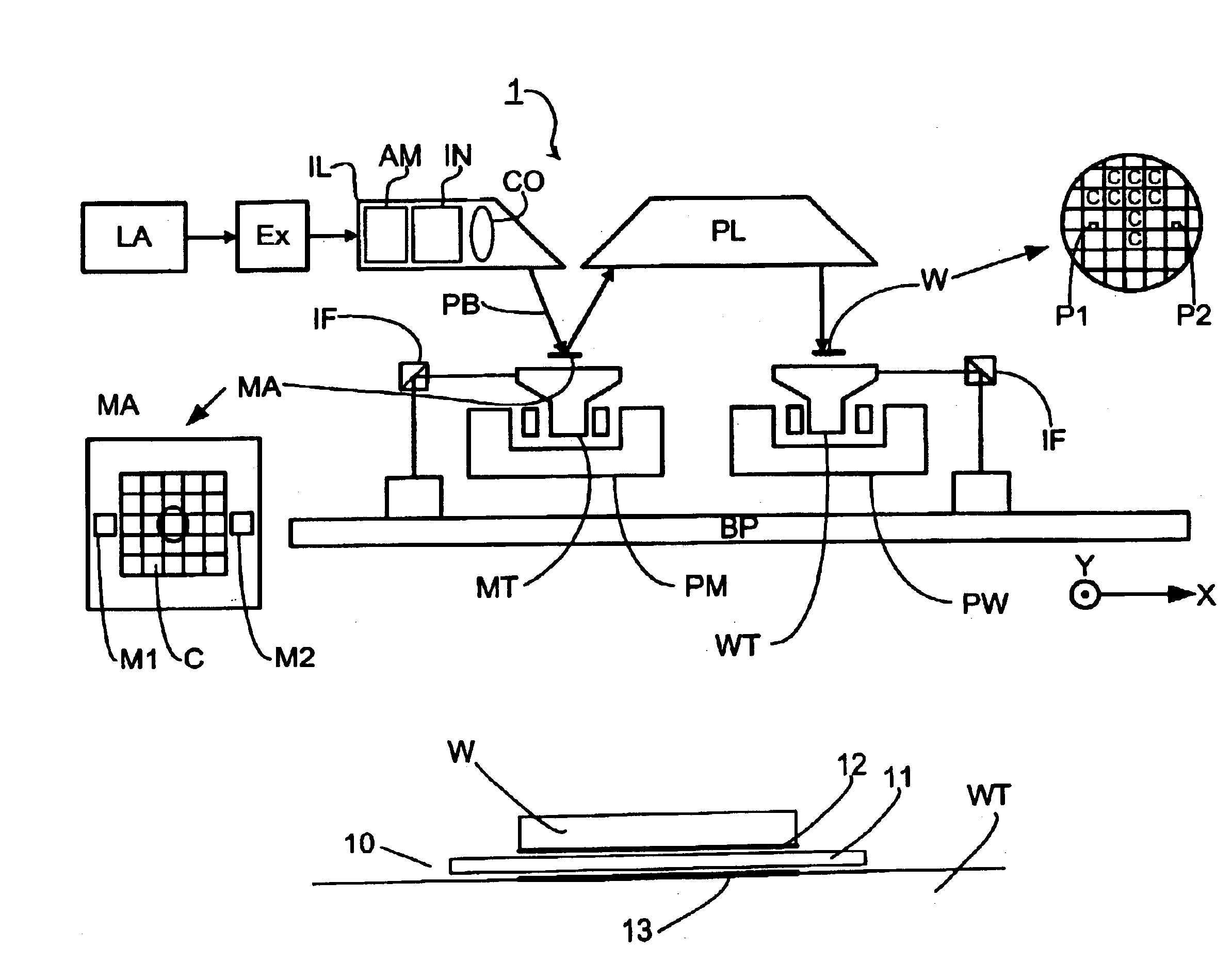
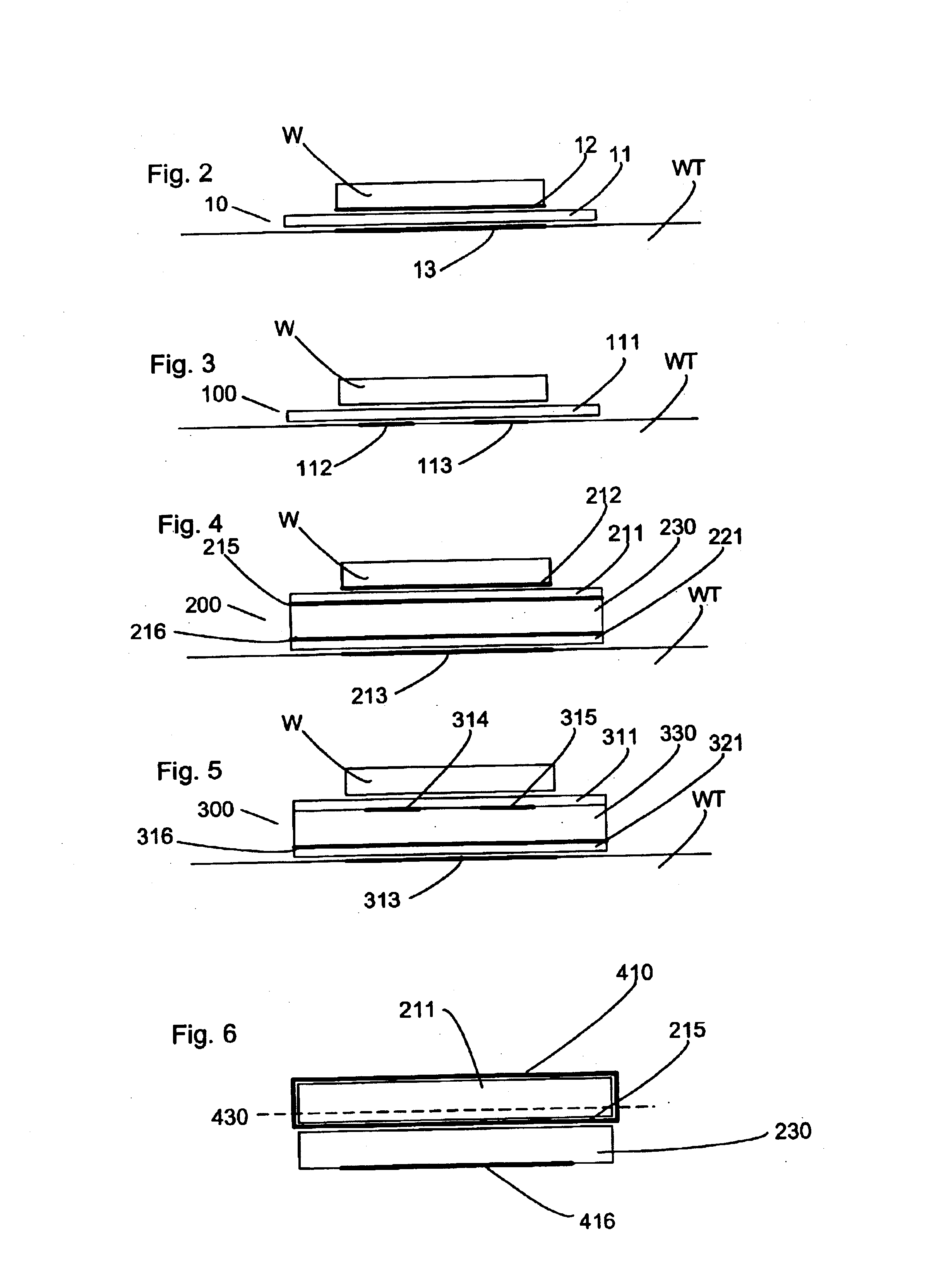
FIG. 2 shows a chuck 10 according to the present invention to hold the substrates W onto the substrate table WT. The chuck 10 includes a member 11 made of a dielectric material. The dielectric member 11 is planar and is polished on either side to the required flatness e.g. requiring no deviations from a perfect plane of greater than, for instance, 200 nm or even higher specification, dependent on the specific application. The dielectric member 11 should have a near zero coefficient of thermal expansion (i.e. less than 0.02×10⁻⁶K−1 (relative expansion / contraction per unit temperature)) so that the position of the substrate W in the apparatus 1 when held on the chuck 10 is not sensitive to temperature fluctuations in the apparatus 1.

An electrode 13 is positioned in or on the substrate table WT and another electrode 12 is positioned on the bottom surface of the substrate W which is to come into contact with a first side of the dielectric member 11. If the substrate W is made of a condu...

fourth embodiment

the present invention is illustrated in FIG. 5. The chuck 300 of the fourth embodiment includes first and second dielectric members 311, 321 and a core 330. An electrode 313 is in the substrate table WT and an electrode 316 is at the bottom of the chuck 300. A first and second electrode 314, 315 are sandwiched between the core 330 and first (the top as illustrated) dielectric member 311 of the chuck 300. The first and second electrodes 314, 315 are in the same plane but are separate from each other and they function to provide a force on the substrate W. The fourth embodiment has the advantages of a separate chuck (e.g. for cleaning) and also of not requiring an electrode to be applied to the bottom surface of the substrate W.

The first (upper as illustrated) surface of the first dielectric member 11, 111, 211, 311 of the chuck onto which the substrate W is placed may be provided with burls (or pimples). The burls have a total surface area that is a small fraction of the total surfac...


PUM


Abstract

A lithographic projection apparatus with a chuck in which a dielectric element of the electrostatic chuck has a specific resistivity of at least 1016 Ωcm so that once the potential difference between electrodes of the chuck is removed the force on the article to be clamped reduces below a predetermined minimum level quickly. The dielectric element also has a coefficient of thermal expansion of less than 0.02×10⁻⁶K−1. A method of manufacturing a chuck includes joining a first glass ceramic element with a second glass element with an electrode therebetween in which a current is passed through the second glass element.

Description

This application claims priority to European Patent Application 02253073.7, filed May 1, 2002, the entire contents of which are hereby incorporated by reference.BACKGROUND OF THE INVENTION1. Field of the InventionThe present invention relates to a chuck, a lithographic projection apparatus, a method of manufacturing a chuck and a device manufacturing method.2. Description of the Related ArtThe term “patterning device” as here employed should be broadly interpreted as referring to device that can be used to endow an incoming radiation beam with a patterned cross-section, corresponding to a pattern that is to be created in a target portion of the substrate. The term “light valve” can also be used in this context. Generally, the pattern will correspond to a particular functional layer in a device being created in the target portion, such as an integrated circuit or other device (see below). An example of such a patterning device is a mask. The concept of a mask is well known in lithogr...

Claims


Application Information

Patent Timeline
IPC IPC(8): G03F7/20H01L21/683H01L21/67H01L21/027H02N13/00
CPCG03F7/707H01L21/6831G03F7/7095G03F7/70708H01L21/027
Inventor VAN ELP, JANGIESEN, PETERVAN DER VELDE, JACOB JAN
Owner ASML NETHERLANDS BV
Why Eureka
Try Eureka