Pattern inspection method and apparatus

Inactive Publication Date: 2005-03-08
HITACHI LTD
View PDF5 Cites 63 Cited by
  • Summary
  • Abstract
  • Description
  • Claims
  • Application Information

AI Technical Summary

Benefits of technology

Accordingly, an object of the present invention is to obviate the aforementioned problem and to provide a pattern inspection method and apparatus using image comparison, in which the chance of detection error of a normal fine pattern is reduced by

Problems solved by technology

Both the prior art 1 and the prior art 2, however, lack the consideration of any means to reduce the chance of erroneously detecting a normal fine pat

Method used


Image

  • Pattern inspection method and apparatus
  • Pattern inspection method and apparatus
  • Pattern inspection method and apparatus

Examples


embodiment 1

(Supplement to Image Comparison Method 3)

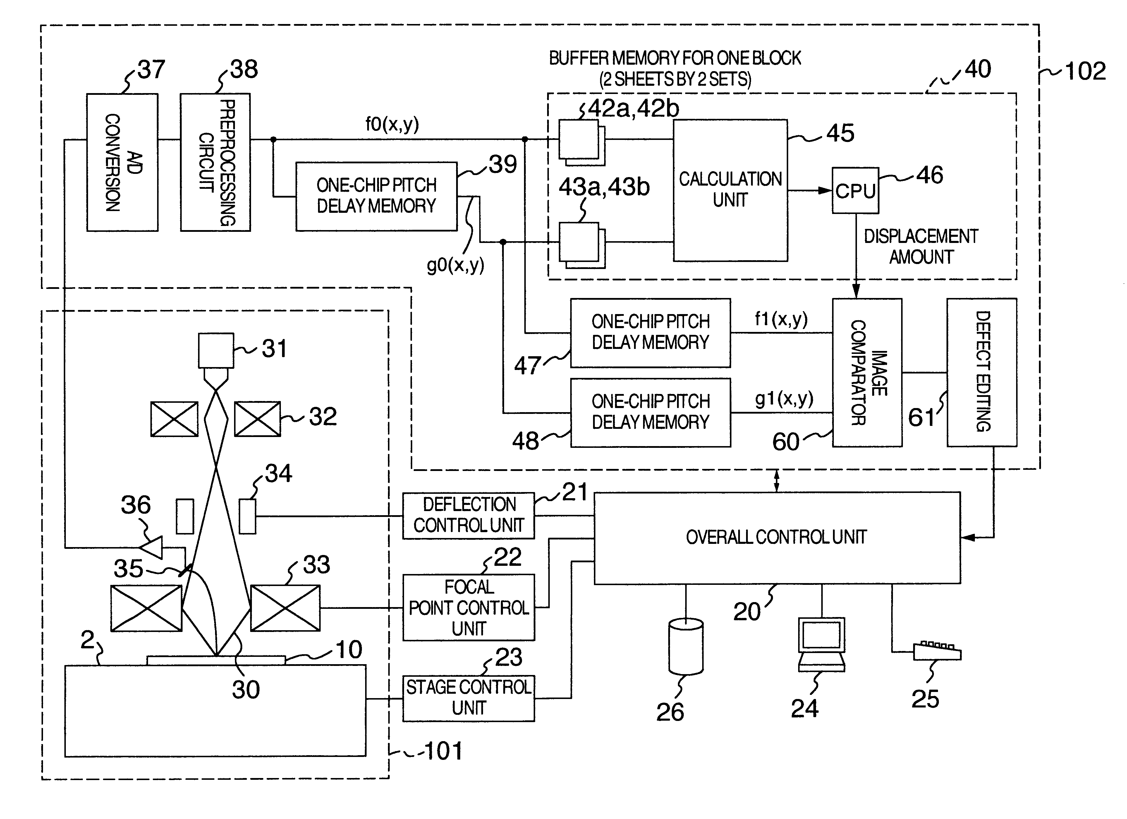
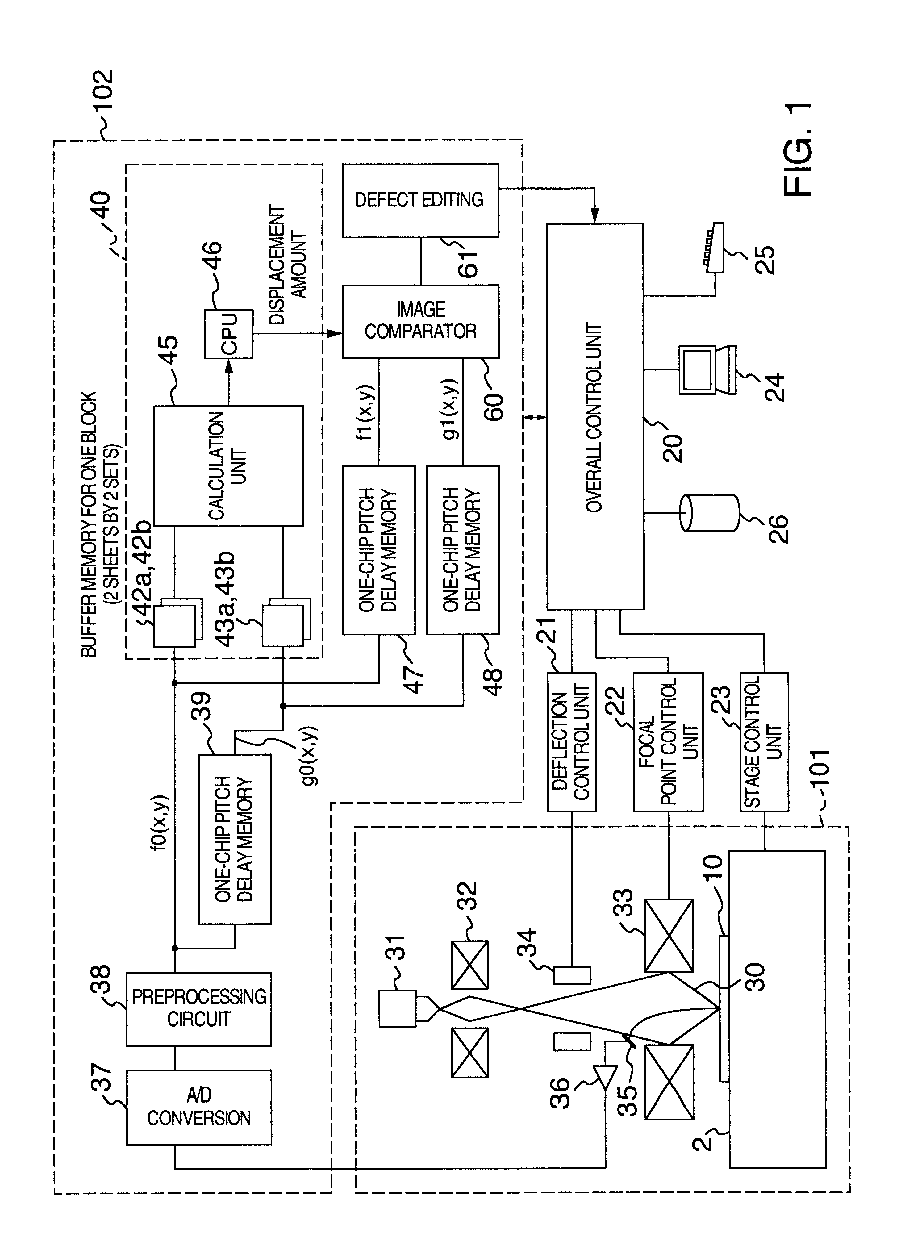
An image comparator unit 60c according to a third embodiment will be specifically described with reference to FIG. 12. In the image comparator units 60a, 60b according to the first and second embodiments, the displacement amount for each block unit area resulting from the operation of the displacement detection unit 40 is used only for position matching at the time of image comparison. In the image comparator unit 60c according to the third embodiment, in contrast, as shown in FIG. 12, such additional information as the number of candidate matching positions for each block unit area or the index of the correctness of the matching positions determined are output from the displacement detection unit 40 in addition to the displacement amount and are input to the threshold value calculation unit 115c and the defect determining unit 116 to be used for image comparison.

The number of candidate matching positions and the period of the pattern includ...

embodiment 2

FIG. 14 is a block diagram showing a configuration of a pattern inspection apparatus according to a second embodiment of the invention.

The second embodiment has exactly the same function as the first embodiment. Unlike in the first embodiment having three delay memories 39, 47, 48 each for one chip pitch, however, the second embodiment has four memories (150a, 150b, 150c, 150d) each capable of storing image data of one chip and used by being switched cyclically by selectors 151, 152, 153.

When the image signal from the detection unit 101 is stored in the memory 150d, for example, the image preceding by one chip is stored in the memory150c, the image preceding by two chips in the memory 150b, and the image preceding by three chips in the memory 150a. While the image signal is being stored in the memory 150d, the displacement between the images of the memory 150c and the memory 150b is detected while at the same time comparing the images of the memory 150b and the memory 150a with each...

embodiment 3

FIG. 15 is a block diagram showing a configuration of a pattern inspection apparatus according to a third embodiment.

Unlike the first and second embodiments which are applicable to both the case in which there exists no matching position and the case in which a matching position cannot be determined as a plurality of matching positions are existent, the third embodiment is mainly applicable to the former case.

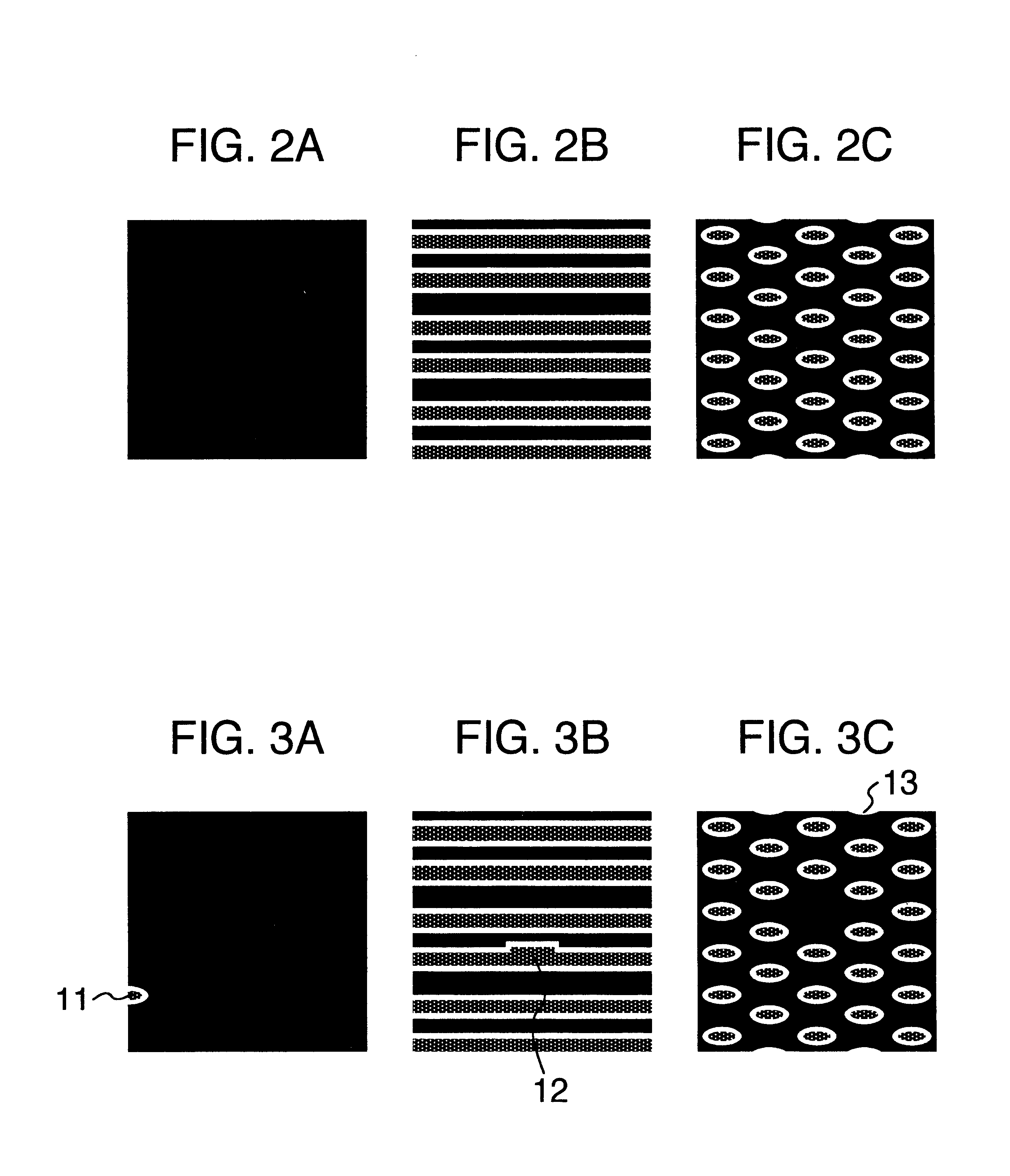
Specifically, the third embodiment is applicable mainly to the case in which an appropriate matching position is set for the block unit area which lacks a pattern or has only a small pattern as shown in FIGS. 2A and 3A or the case in which a pattern exists only in horizontal direction or only a small pattern exists in other than the horizontal direction, and therefore the matching position in X direction cannot be determined, or the matching position in Y direction cannot be determined for similar reason.

The third embodiment is also intended to reduce the error included in the ...


PUM


Abstract

A pattern inspection method and apparatus are disclosed, the method has the steps of generating a reference digital image signal to be compared with a detection digital image signal detected continuously from the desired band-shaped inspection area on an object to be inspected, determining zero or one or more candidate , matching positions between the detection digital image signal and the reference digital image signal for each block unit area sequentially cut out and calculating a mass of candidate matching positions over the entire band-shaped inspection area, determining an accurate matching position between the detection digital image signal and the reference digital image signal for each block unit area based on the continuity of the block unit areas from the calculated mass of candidate matching positions over the entire band-shaped inspection area, and determining a defect by matching the positions based on the determined accurate matching position for each block unit area and comparing the images.

Description

BACKGROUND OF THE INVENTIONThe present invention relates to a pattern inspection method and apparatus for producing an image of an object such as a semiconductor wafer, a TFT or a photomask using an electron beam or light and comparing the image-with a reference image stored in advance thereby to detect a defect, or in particular to a pattern inspection method and apparatus suitable for inspecting a semiconductor logic product using the electron beam.The prior art disclosed in JP-A-5-6928 (prior art 1) and JP-A-10-74812 (prior art 2) for pattern inspection to detect a defect by comparing continuously input canditate (object) images with a reference image are well known.The prior art 1 concerns a pattern inspection method and apparatus in which the shift amount (displacement amount) between a detection binarized edge signal indicating a detection edge pattern from a detection image signal detected by a linear image sensor and a reference binarized edge signal indicating a reference e...

Claims


Application Information

Patent Timeline
IPC IPC(8): G01N21/88G06K9/00G06T1/00G06T7/00H01L21/66G01N21/956
CPCG06T7/001G06T2207/30148
Inventor SHISHIDO, CHIEWATANABE, MASAHIROTAKAGI, YUJIMIYAI, HIROSHI
Owner HITACHI LTD
Why Eureka
Try Eureka