
Athermal optical coupler

Active Publication Date: 2005-03-08
LUMENTUM OPERATIONS LLC
View PDF20 Cites 9 Cited by
  • Summary
  • Abstract
  • Description
  • Claims
  • Application Information

AI Technical Summary

Benefits of technology

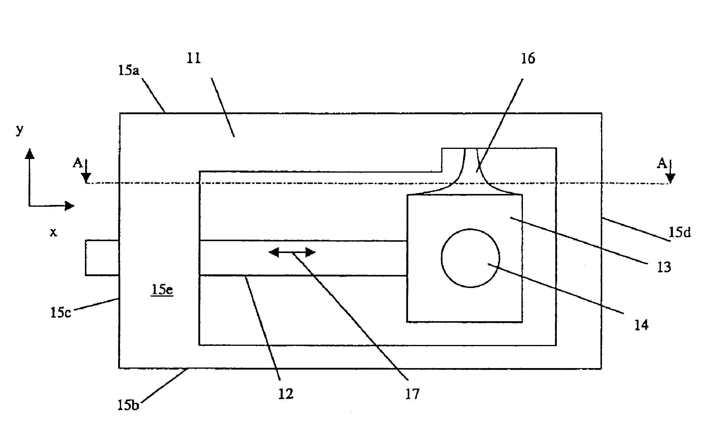
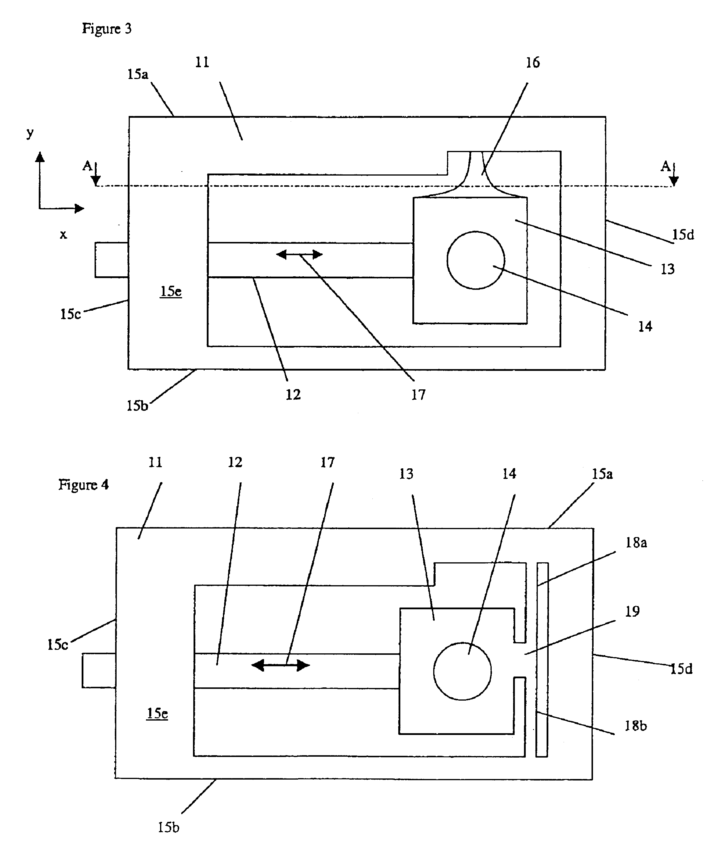
Another aspect of the present invention relates to a device for optically coupling a first waveguide to a second waveguide via a lens for transmitting an optical signal defined by a center wavelength therebetween, comprising:frame means for mounting in a fixed position relative to said first waveguide;an expansion element, one end of which is connected to said frame means, for expanding or contracting in an expansion direction in response to a temperature change, said expansion element having a coefficient of thermal expansion higher than said frame means;a waveguide block flexibly connected to said frame means and engaged with another end of said expansion element for supporting the lens relative to said first waveguide;whereby a shift in the center wavelength due to a change in ambient temperature is at least partially compensated for by movement of the lens relative to the first waveguide caused by the expansion or contraction of said expansion element.
Yet another feature of the present invention relates to a device for optically coupling a first wavegui

Problems solved by technology

Unfortunately, a change in ambient temperature causes a change in the properties of the waveguides, e.g. index of refraction, and therefore a shift in the center wavelength of signals transmitted therein.
Without active temperature stabilization, changes in temperature encountered in use cause changes in the properties of the waveguides, e.g. the index of refraction, which results in shifts in the center wavelengths of the channels in the output signal.
Because of their cantilevered construction, the outer free ends of these devices are completely unrestrained in any direction.
Accordingly, they can be relatively unstable, especially over time.
Unfortunately, these applications only disclose spring elements extending in the expansion direction of the expansion arm, and fail to provide the means to restrict the end of the expansion arm from vibrating perpendicularly to the expansion direction.

Method used


Image

  • Athermal optical coupler
  • Athermal optical coupler
  • Athermal optical coupler

Examples


second embodiment

the present invention, illustrated in FIG. 4, is similar to the aforementioned embodiment except that the flexible arm 16 is replaced with a pair of flexible arms 18a and 18b, joined to the side of the waveguide block 13 opposite the expansion element 12 at joint 19. With this arrangement, the waveguide block 13 is completely restrained from moving in the y direction, i.e. perpendicular to the expansion direction 17, by an arm on either side thereof. The arms 18a and 18b are preferably planar, web-like members joined to the upper frame member 15a and the lower frame members 15b, respectively, and extending from the front face 15e of the frame 11 to the rear face 15f. With this arrangement, the frame 11, the arms 18a and 18b, and the waveguide block 13 can be constructed from a single block of low CTE material. The manufacturing process starts by milling out the voided areas from the front face 15e through to the rear face 15f, thereby making only the front and rear faces 15e and 15f...


PUM


Abstract

The invention relates to an optical coupling device that provides passive compensation for a shift in center wavelength due to a change in ambient temperature. A conventional solution is to mount one of the elements to be coupled on a pedestal or cantilevered arm, which has a coefficient of thermal expansion (CTE) different from a frame fixed relative to the other of the elements to be coupled. Unfortunately, these devices do not provide consistent results over long periods of time, due to uncontrolled movement of the outer free end of the cantilevered arm or pedestal. The present invention provides an expansion arm fixed on one end to a frame, a holder on the other end of the expansion arm, and a pair of flexible arms connecting the holder to the frame. This arrangement enables the expansion arm to freely expand in a first direction, while greatly restricting movement in any other direction. The present invention also relates to a optical coupling device that includes a expansion arm with an adjustable effective length. Furthermore, optical coupling devices are disclosed that include an expansion arm for moving a lens relative to one or more waveguides providing thermal compensation.

Description

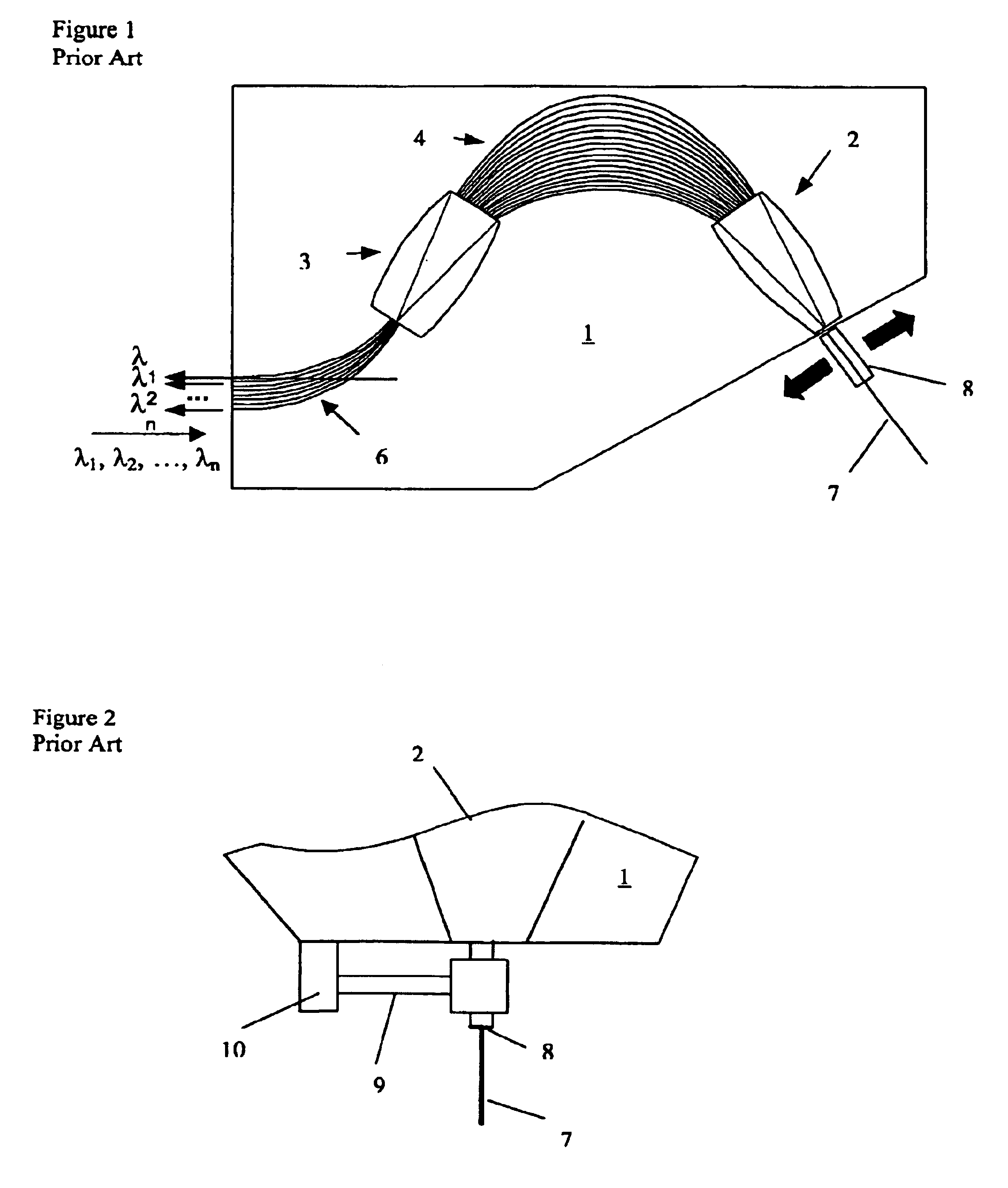
TECHNICAL FIELDThe present invention relates to optical coupling between waveguides, and in particular to an optical coupler for coupling light between a slab waveguide and an optical fiber which is able to compensate for changes in temperature.BACKGROUND OF THE INVENTIONConventional devices used for optical coupling between waveguides, particularly between an integrated waveguide and an optical fiber, have dealt primarily with aligning the different waveguides to obtain maximum optical coupling at room temperature. Unfortunately, a change in ambient temperature causes a change in the properties of the waveguides, e.g. index of refraction, and therefore a shift in the center wavelength of signals transmitted therein.A conventional slab-launched array waveguide grating (AWG), illustrated in FIG. 1, is integrated into a substrate 1, and includes a first slab waveguide 2 and a second slab waveguide 3, which are optically connected by an array of discrete waveguides 4. A plurality of di...

Claims


Application Information

Patent Timeline
IPC IPC(8): G02B6/34G02B6/30G02B6/26G02B6/32G02B6/36
CPCG02B6/12016G02B6/1203G02B6/30G02B6/32G02B6/26G02B6/36
Inventor SAMIEC, DIRKKOERDT, MICHAELOLIVER, STEVENMILINKOVIC, VLATKO
Owner LUMENTUM OPERATIONS LLC
Learn More