
Area based position determination for terminals in a wireless network

a wireless network and terminal technology, applied in direction finders, instruments, transmission monitoring, etc., can solve the problem that the position fix calculated using the position-domain technique is less accurate than the range-domain position fix, and achieve the effect of accurate estimation of the approximate position of the terminal

Inactive Publication Date: 2005-03-08
QUALCOMM INC
View PDF16 Cites 434 Cited by
  • Summary
  • Abstract
  • Description
  • Claims
  • Application Information

AI Technical Summary

Benefits of technology

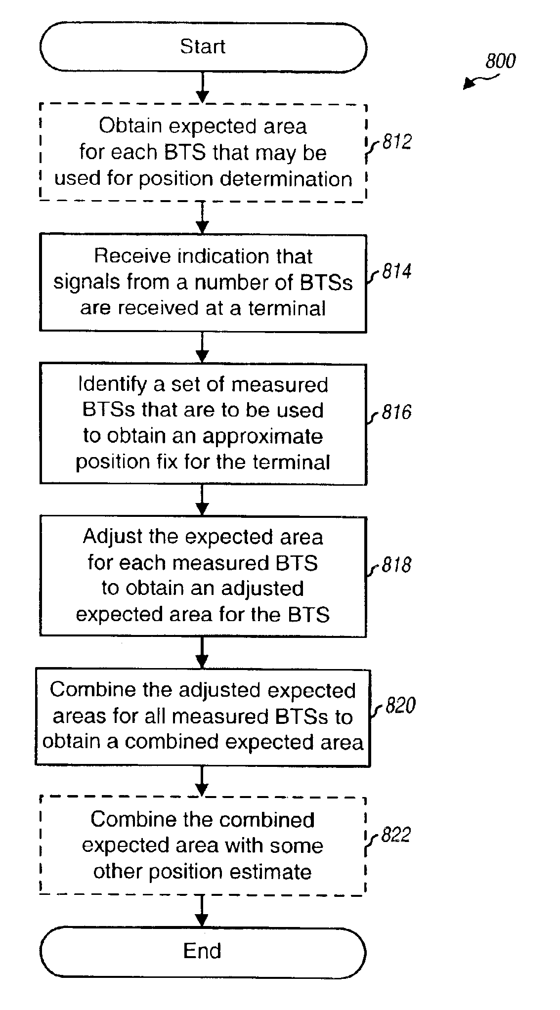
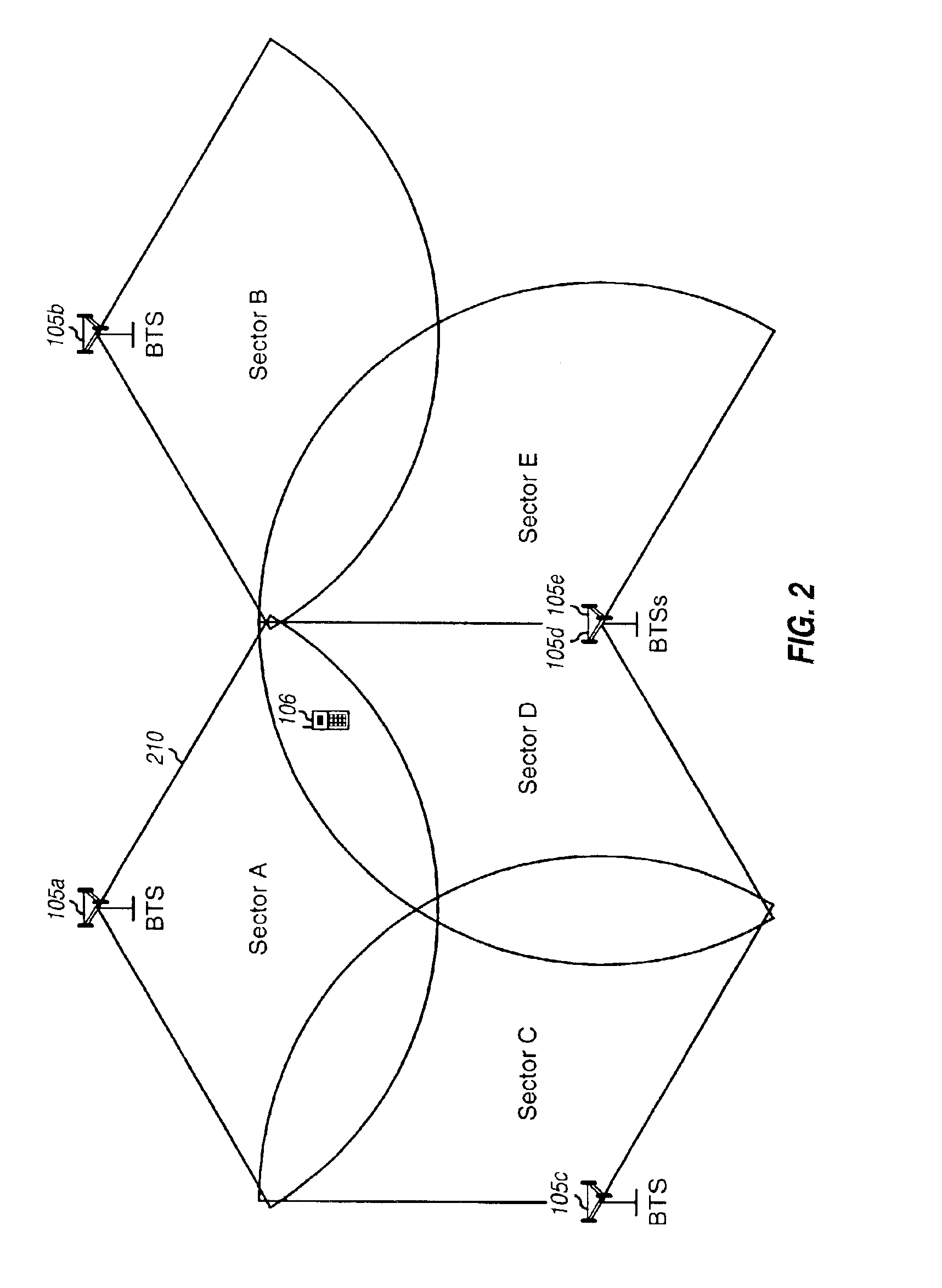
This document describes a method and apparatus that more accurately estimates the approximate position of a terminal in a wireless network. In one embodiment of the method and apparatus, the terminal's approximate position is estimated based upon an “expected area” associated with a “reference base transceiver subsystem (BTS)”. The reference BTS may be any BTS with which the terminal is in communication. The expected area associated with a BTS is an area within which a terminal is likely to be located given that it can receive signals from the BTS. The expected area is: (1) a location that may be provided as the estimated position of the terminal, and (2) an area within which the terminal is likely to be located, where the likelihood may be given by a particular percentage. The expected area associated with each BTS may be modeled based on various parameters, such as the location and orientation of the BTS antenna, maximum antenna range (MAR), and so on.

Problems solved by technology

A position fix calculated using the position-domain technique is less accurate than a range-domain position fix.

Method used


Image

  • Area based position determination for terminals in a wireless network
  • Area based position determination for terminals in a wireless network
  • Area based position determination for terminals in a wireless network

Examples


Embodiment Construction

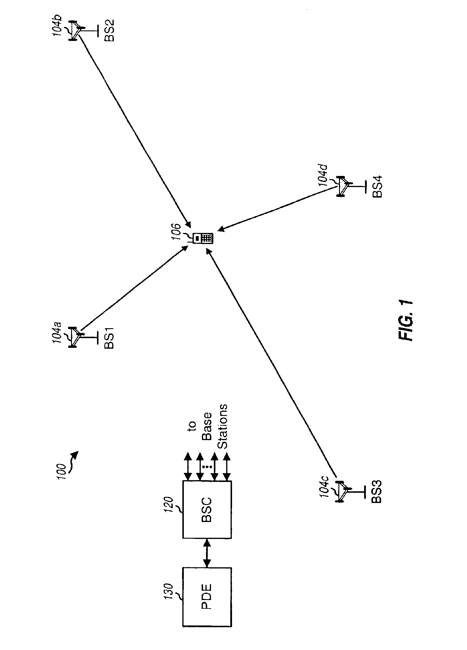
FIG. 1 is a diagram of a wireless communication network 100, which may be a code division multiple access (CDMA) network, a time division multiple access (TDMA) network, a frequency division multiple access (FDMA) network, or another type of wireless communication network. A CDMA network may be designed in accordance with one or more CDMA standard systems, such as an IS-95 system, a IS-2000 system, or a W-CDMA system. A TDMA network may be designed in accordance with one or more TDMA standard systems, such as a GSM system. The details of these standard systems are well known in the art.

Network 100 includes a number of base transceiver subsystems (BTSs) 104, with each BTS 104 serving a particular geographic area. Only four BTSs 104a through 104d are shown in FIG. 1 for simplicity. The coverage area of a BTS is often referred to as a “cell”. The coverage area is that area within which a terminal receives signals from the BTS 104. The size and shape of a cell is typically dependent on ...


PUM


Abstract

Techniques to estimate the position of a wireless terminal. In a method, the identities of a number of transmitters (e.g., BTSs) to be used to estimate the position are initially received. Expected areas for these transmitters are then determined. The expected area associated with each transmitter is indicative of an area where the terminal is likely to be located given that the signal from the transmitter is received by the terminal. Each expected area may comprise a location (e.g., the expected area center) to be used as an estimated position of the terminal and an uncertainty (or error estimate) associated with that estimated position. The expected areas for the transmitters are then combined (e.g., based on a weighted average) to determine a combined expected area, which is then provided as the estimate of the position of the terminal.

Description

BACKGROUND1. FieldThe presently disclosed subject matter relates generally to position determination and more specifically to a method and apparatus for performing area based position determination for terminals in a wireless network.2. BackgroundIt is often desirable, and sometimes necessary, to know the position of a wireless user. For example, the Federal Communications Commission (FCC) has adopted a report and order for an enhanced 911 (E-911) wireless service that requires the location of a wireless terminal (e.g., a cellular phone) to be provided to a Public Safety Answering Point (PSAP) each time a 911 call is made from the terminal. In addition to the FCC mandate, a service provider may provide various applications using location services (i.e., services that identify the position of a wireless terminal). Such applications may include, for example, location-sensitive billing, asset tracking, asset monitoring and recovery, fleet and resource management, personal-location serv...

Claims


Application Information

Patent Timeline
Patent Type & Authority Patents(United States)
IPC IPC(8): G01S5/02G01S5/14H04Q7/38G01S19/25H04W64/00
CPCG01S5/0252H04W64/00G01S5/14
Inventor RILEY, WYATT
Owner QUALCOMM INC
Learn More