Electronic self-destruct device

a self-destructing device and electronic technology, applied in the direction of time fuzes, ammunition fuzes, weapons components, etc., can solve the problems that the application of self-destructing in general is not possible, and achieve the effect of reducing the number of structural parts, and maximizing simplicity

Inactive Publication Date: 2005-03-15
JUNGHANS MICROTEC
View PDF10 Cites 11 Cited by
  • Summary
  • Abstract
  • Description
  • Claims
  • Application Information

AI Technical Summary

Benefits of technology

Therefore, a circuit is to be provided which, on the one hand, is of maximum simplicity and therefore as much as possible energy-saving, cost-efficient and at the same time (due to reduced number of structural parts) is reliable and which, on the other hand, permits realization the time function with RC networks independently of a fluctuating supply voltage level.

Problems solved by technology

The problem of such an energy supply lies in the case of utilization of the electronic circuitry for the realization of a highly precise time function.
However, the oscillation frequency of RC oscillators is highly dependent on the operating voltage such that application for a self-destruction, in general, is not possible.

Method used


Image

  • Electronic self-destruct device
  • Electronic self-destruct device

Examples


Embodiment Construction

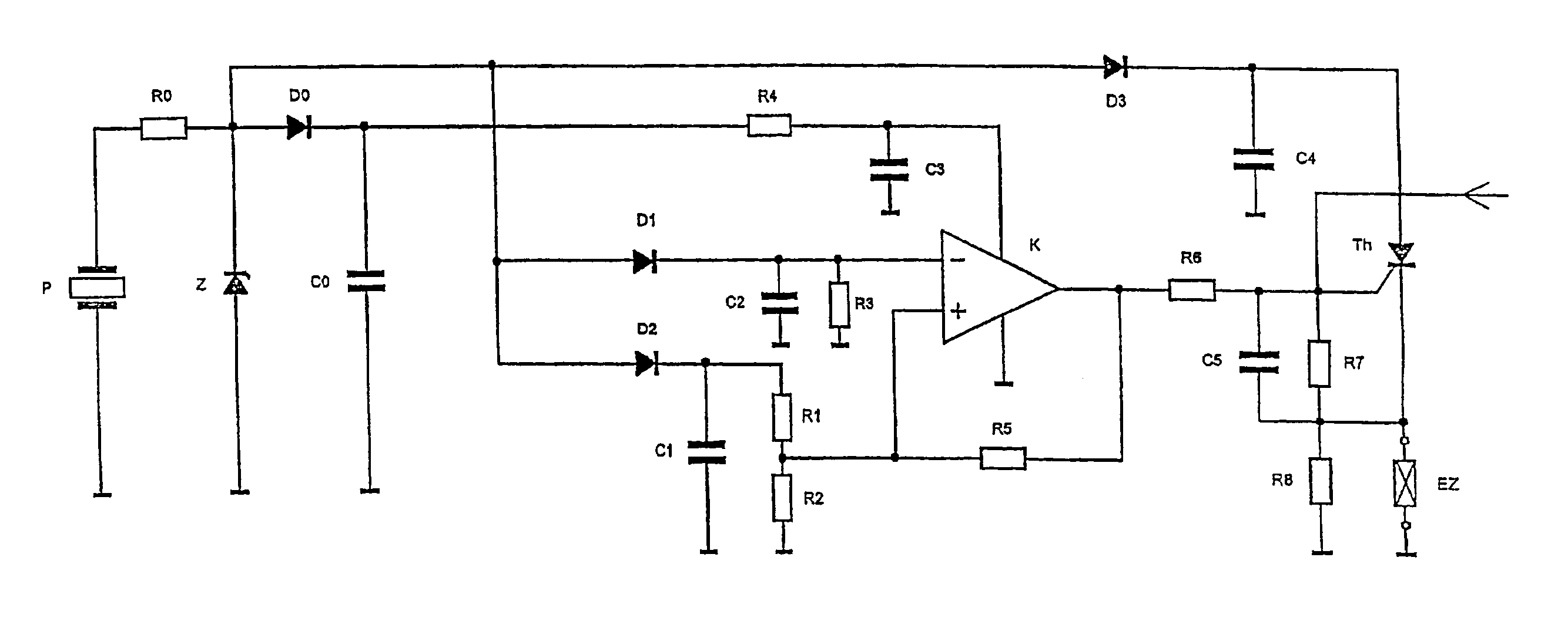
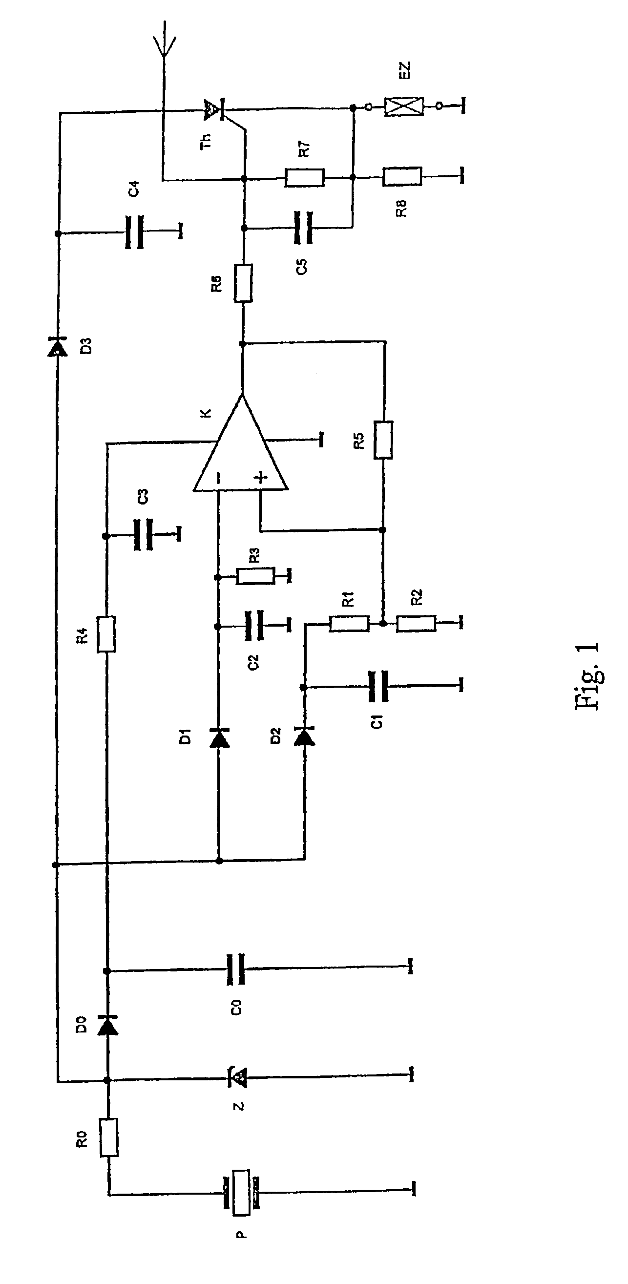
In FIG. 1, capacitors C0 to C4 are charged during the firing via a piezo element P a voltage generator, a dropping resistor R0, a Zener diode Z (for voltage limitation) and diodes D0 to D3. Delayed across resistor R4 and the second storage capacitor C3, the charged capacitor C0 subsequently provides the supply voltage for the operation of a comparator K. The comparator K is a commercially available integrated [circuit] package with extremely low current consumption (<1 μA), very low input currents (<pA) and a common mode range extending up to the limits of the operating voltage.

The delayed provision of the operating voltage is to prevent a malfunction during the barrel passage phase and the capacitor C3 charged with delay supplies at the point in time of the ignition the energy for driving the thyristor Th. The ignition capacitor C4 is charged across diode D3, and remains at a sufficient voltage level until the ignition of the thyristor Th. For realizing a time function in...


PUM


Abstract

A device provides for time-controlled self-destruction of a projectile by a batteryless, electronic self-destruct device. Several capacitors charged by a piezo element or a surge generator during firing are used in the flight phase for operational purposes. At least two of the capacitors are connected to the input of a comparator, so that the influence of a constantly modifiable operational voltage and the influence of a discharge of modifiable voltage levels by the piezo element or surge generator does not affect the time function.

Description

BACKGROUND OF THE INVENTION1. Field of the InventionThe present invention relates to a configuration for an electronic self-destruct device in a projectile detonator without the use of a battery installed in the detonator.2. Description of the Related ArtApart from the main detonation criteria, such as impact or time function, for today's projectile or submunition detonators frequently a self-destruction function is also demanded, which also ignites the explosive in the absence of a response of the primary ignition criteria after the passage of a maximum function time. This function, parallel to the other ignition criteria, is intended to limit the danger range of the munition in the firing direction and / or minimize the occurrence of dud shots. This makes utilization in previously conquered territories safer due to the lower danger through one's own duds. This function also permits, on the other hand, the bombardment of an encircled enemy without endangering opposing troops of one's...

Claims


Application Information

Patent Timeline
Patent Type & Authority Patents(United States)
IPC IPC(8): F42C15/44F42C11/06F42C9/00F42C15/00F42C11/00F42C11/02F42C9/16
CPCF42C9/16F42C15/44F42C11/06F42C11/02
Inventor KOLBLI, BERTRAM
Owner JUNGHANS MICROTEC
Why Eureka
Try Eureka