Leak detection with thermal imaging

Inactive Publication Date: 2005-03-15
CARRIER CORP
View PDF35 Cites 55 Cited by
  • Summary
  • Abstract
  • Description
  • Claims
  • Application Information

AI Technical Summary

Benefits of technology

By yet another aspect of the invention, a black body is placed behind the coil to prevent the reflection of light that would otherwise introduce errors into the imaging process.
By still another aspect of the in

Problems solved by technology

The cost of the testing process is dictated not only on the original equipment initial costs, but on the cost of use of the trace gas in itself.
The very nature of this approach imposes a potential impact on the factory environment due to the escape of gas and non-contained leakage points.
Trace gas escapes to the factory environment are greatly undesirable not only because they represent waste in t

Method used


Image

  • Leak detection with thermal imaging
  • Leak detection with thermal imaging
  • Leak detection with thermal imaging

Examples


Embodiment Construction

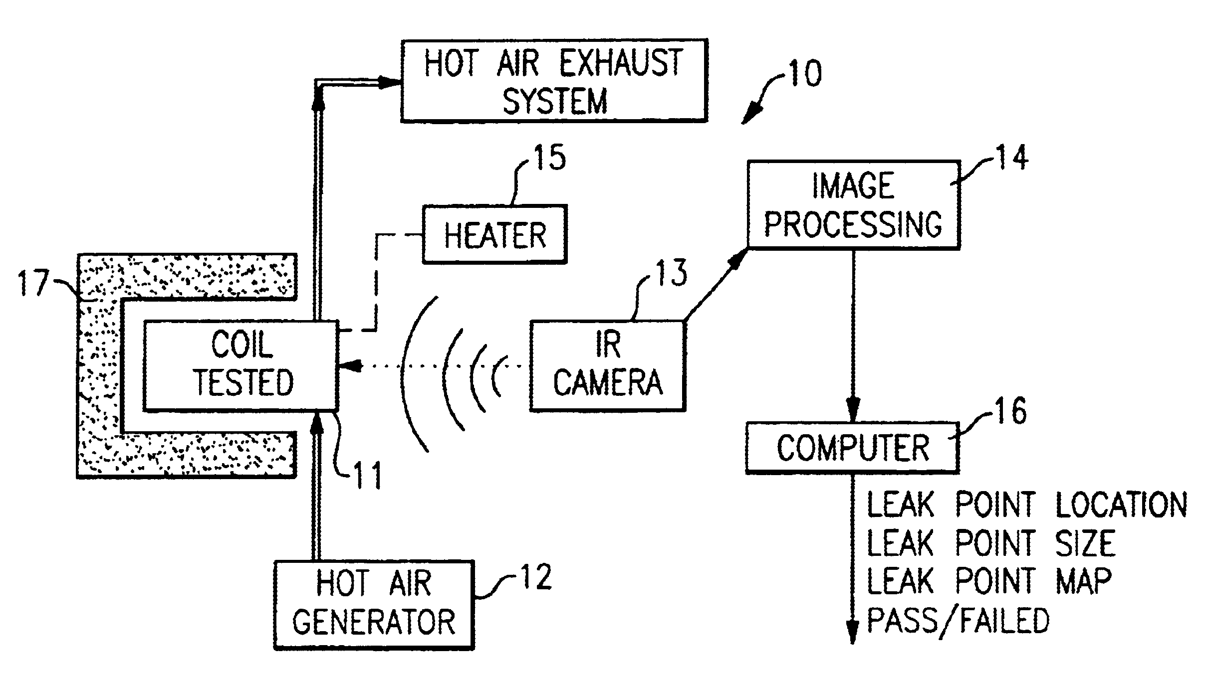
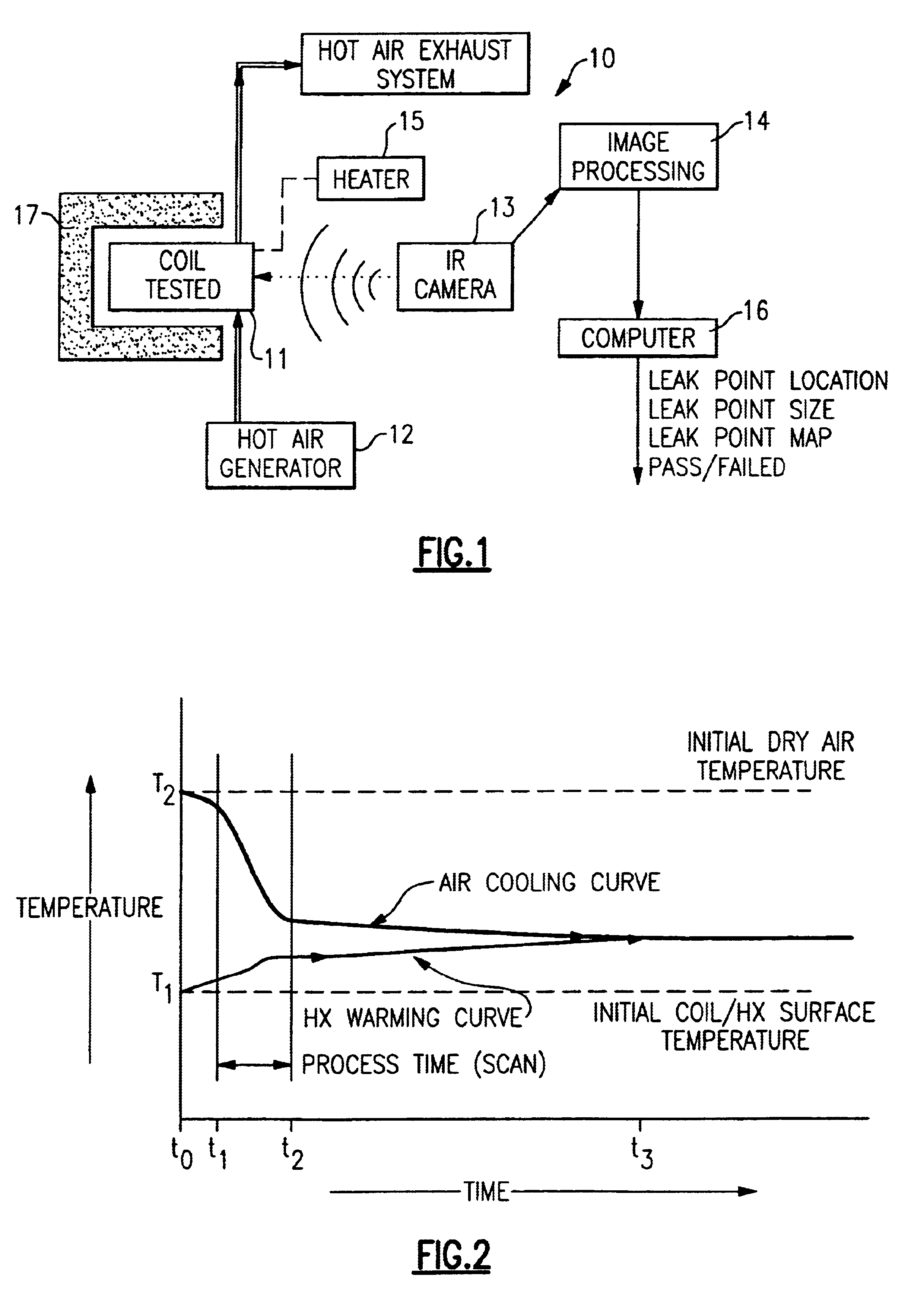
Referring now to FIG. 1, the invention is shown generally at 10 as applied to a heat exchanger or coil 11 to be tested. The coil 11 is pressurized by a compressor or pump indicated generally in FIG. 1 as a hot air generator 12 to a relatively low pressure such as 5 psi, for example. A preferred gas medium is ambient air.

An infra-red camera 13 is set up in the vicinity of the coil 11 such that it can detect any leakage from the coil 11 by the temperature difference between the coil 11 and the escaping vapor. In order to expose the various locations of possible leakage from the coil 11, it will generally be necessary to move either the coil 11 or the camera 13. If the coil is moved, the camera 13 can remain stationary while a programmed fixture can be made to automatically move the coil 11 to the various positions that will enable the camera 13 to be aimed at the possible areas of leakage. In the alternative, the coil 11 may remain stationary, with the camera 13 being moved in a progr...


PUM


Abstract

An infrared camera is used to detect leakages in a heat exchanger by an imaging process that indicates temperature differences between a heat exchanger and a pressurized gas therein. The temperature differences are created by cooling or heating either the pressurized gas or the heat exchanger, and any leakages are visually observable by the resultant image which is representative of the temperature differences. The process can be accomplished with the use of ambient air rather than the commonly used trace gases which are less desirable because of economical and environmental reasons.

Description

BACKGROUND OF THE INVENTIONThis invention relates generally to heat exchangers for air conditioning systems and, more particularly, to a method and apparatus for leak testing of heat exchangers to be charged with refrigerant.There are many different ways of testing the integrity of a coil or heat exchanger used in residential, commercial or industrial air conditioning and heating systems, but all of them require the use of a trace gas and a surrounding matrix against which escape of the trace gas is detectable either visibly or by the use of instruments. Such trace gases, ranging from refrigerants to inert gases, are used either to pressurize the component prior to leak detection of the outer geometry of the part or forming a surrounding environment on the component itself while the latter is subject to internal vacuum.The cost of the testing process is dictated not only on the original equipment initial costs, but on the cost of use of the trace gas in itself. The very nature of th...

Claims


Application Information

Patent Timeline
IPC IPC(8): G01M3/00
CPCG01M3/002F24F2011/0084F24F11/36
Inventor AVILA, LUIS F.
Owner CARRIER CORP
Why Eureka
Try Eureka